The AMA Alpha Background
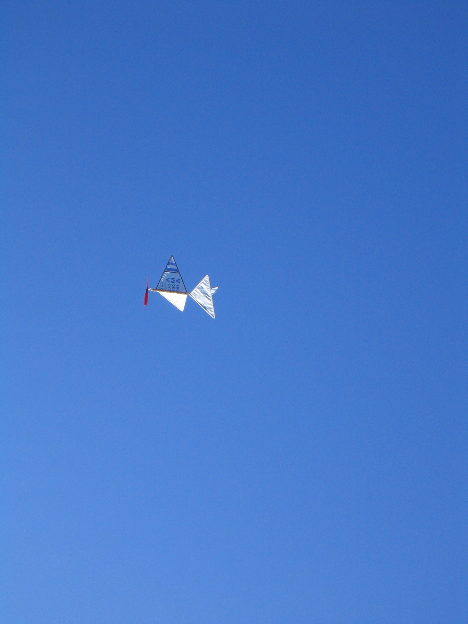
The Academy of Model Aeronautics (AMA) promoted the AMA Cub as its beginning model airplane for many decades. Millions of them have been built and flown. It teaches many basic skills of aeromodelling; plan reading, cutting and gluing balsa and paper, making and winding a rubber motor, flight trimming. The AMA Cub does not meet the requirements of modern classrooms. It takes longer to build than the time available in most class sessions. Razor blades, pins and model airplane glue are not welcome in many schools.
The AMA Education Committee developed the AMA Alpha to better fit into the AMA school and Science Olympiad programs. They patterned it on the 14″ North Pacific Sleek Streek, which was wildly popular among young people of my generation (“Baby Boomers”).
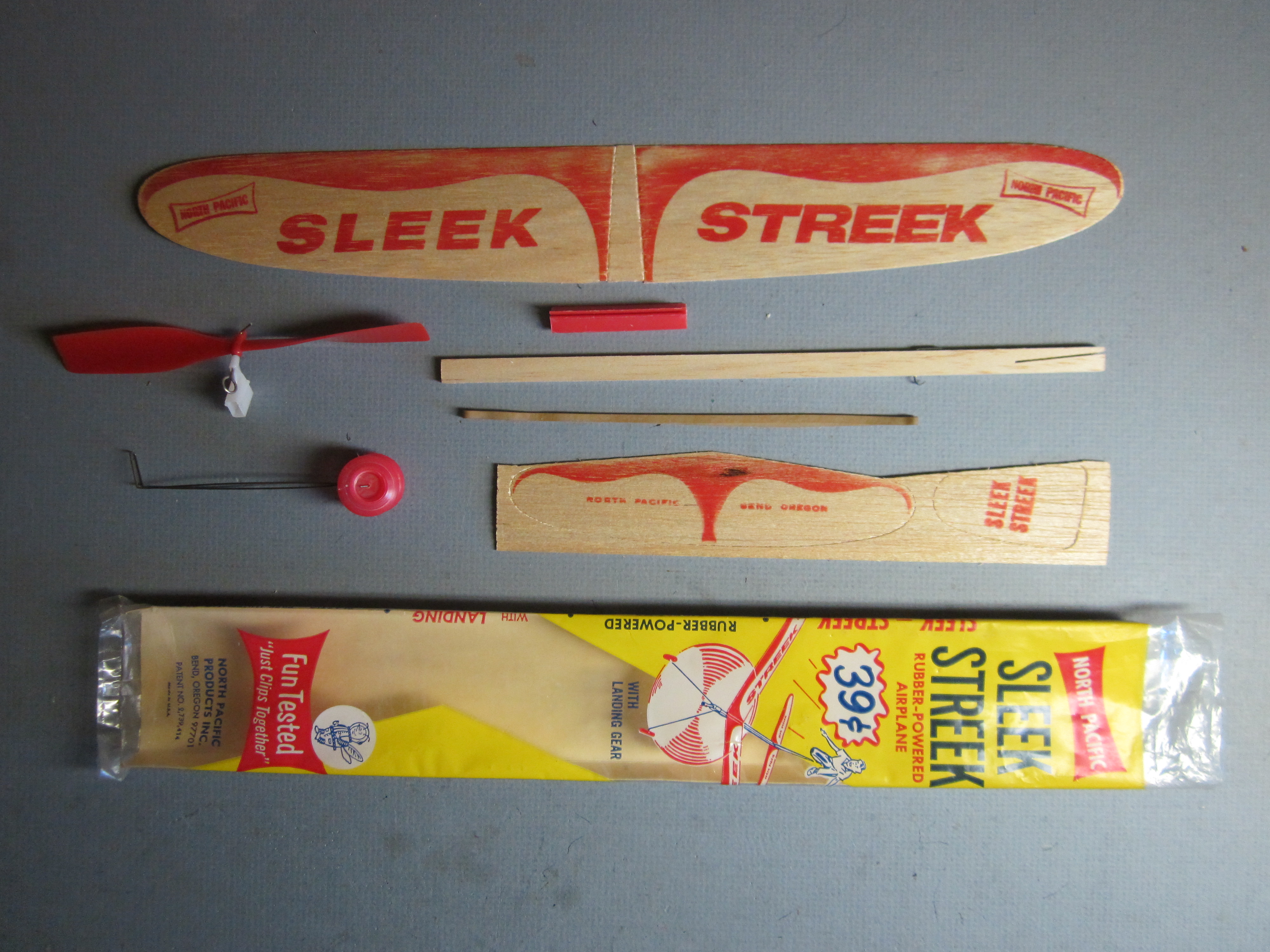
With 9 parts and a four part instruction sequence, this airplane clips together in a very short time. No cutting or gluing required. No need to wait for glue to dry.
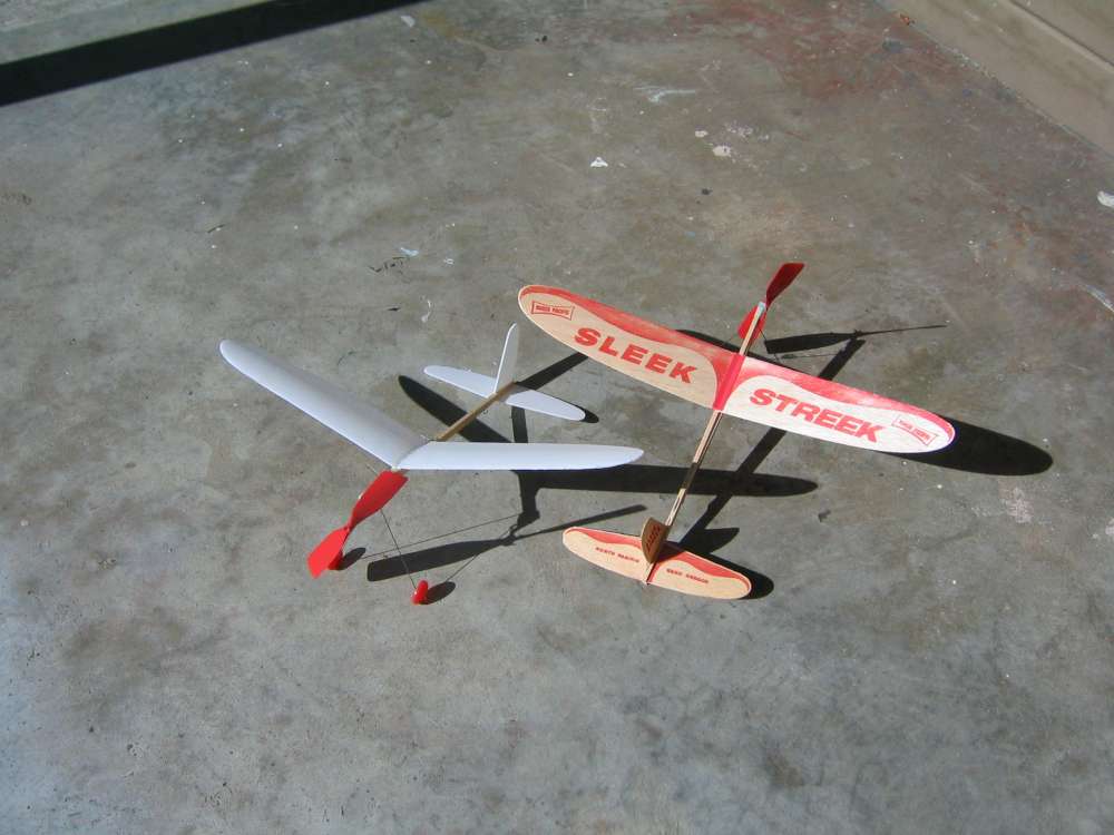
The wing clip allows you to move the wing along the stick to adjust the wing position to best align the center of gravity. The Sleek Streek was an excellent flyer. It also had landing gear for ROG (Rise Off Ground) flights.
Unfortunately, North Pacific went out of business in the early 70’s.
This picture also shows a Sleek Streek I made (2009) using sheet foam. It has a curved balsa wing saddle that maintains camber across the center of the wing. This was the one defect of the North Pacific wing clip. That flat section across the middle of the wing spoils the wing aerodynamics. It is also not structurally suitable for soft foam wings. The flat foam bends too easily. A cambered wing is stiffer.
AMA Alpha Appears
The AMA Alpha was first publicly displayed at the AMA Expo West on January 6-8, 2017, at the Ontario Convention Center in Ontario , California, and then at the AMA Expo East on February 24-26, 2017, at the Meadowlands Exposition Center in Secaucus, New Jersey.
A video from the Expo gave us a brief glimpse of the new AMA Alpha. There were no details available, no dimensions. My immediate impression was that the propeller was too small and the straight North Pacific wing clip would be a problem with foam wings.
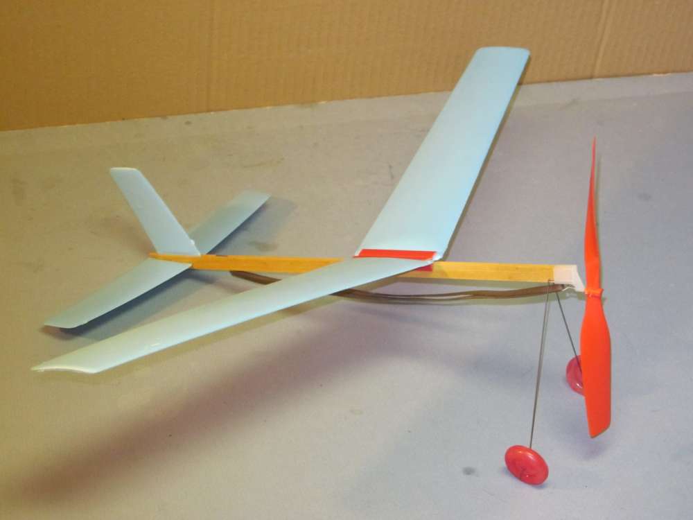
The new AMA Alpha is closer in size to the North Pacific 18 1/4″ Sky Master.
Foam thin enough to fit into those clips is not as stiff as sheet balsa and will fail. That is what happened to North Pacific. They replaced the balsa wings with tuffoam, the wings failed, people stopped buying their products and North Pacific went out of business.
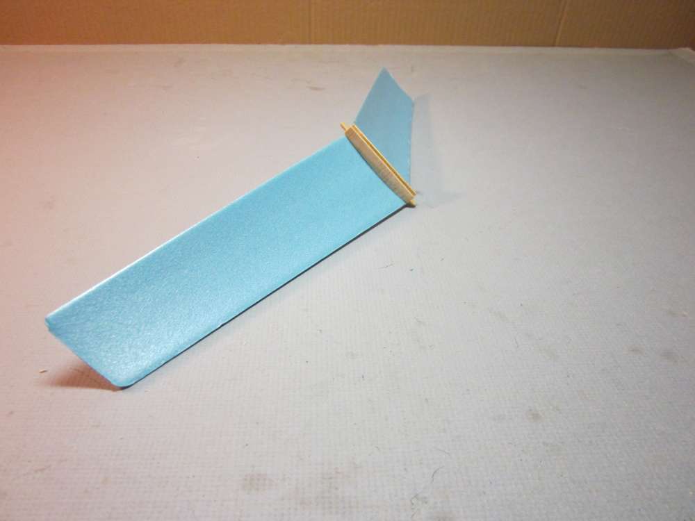
I replaced the straight plastic wing clip with a cambered balsa wing saddle. I had to shorten the wing a bit to get into the cambered part, but the wing is much stronger because of the curvature and it is aerodynamically much better as well. A flat section in the center of the wing disturbs the continuity of the circulation which produces the lift on the wing.
This has worked well on sheet foam wings for several of the planes I have shown on EndlessLift; Sierra Nevada Special, Snowflake, Cloud Tramp.
I shared my concerns with the AMA Education Committee and asked how soon I would be able to get my hands on an AMA Alpha.
The new AMA Alpha was introduced in the May 2017 Model Aviation in Bill Pritchett’s “Education Through Aviation” column.
It appeared in a video.
It was posted on the AMA Flight School page. This link tells a little more about the design specification and how it will fit better into the AMA school and Science Olympiad programs. It also has links to lesson plans. Use in the AMA school program was a major motivation for developing the AMA Alpha. This page now includes a link to the AMA Store, where you can buy an AMA Alpha kit, and a building video. Educators may also buy bulk packs from the AMA Education Department at reduced cost.
Finally, after a long wait, they were made available from the AMA Store. The amazingly low $7.95 price is due to heavy subsidies of development and tooling by the AMA. This airplane was designed by successful competition flyers, so it will fly, not just look good. This is not the usual toy airplane. And it includes a 20:1 winder, so the motor may be properly wound for long flights.
Bill Kuhl has published a review with flight videos.
Quick Review
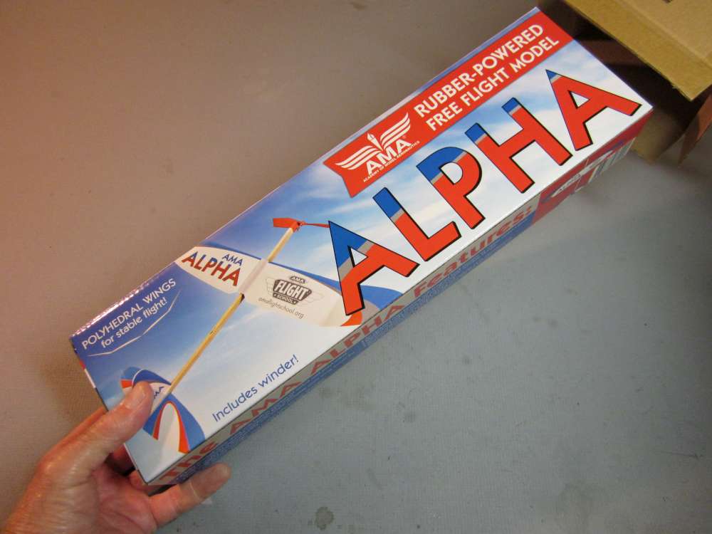
An unexpected package arrived in the mail on Monday, 24. October, 2017, from the AMA. It was an AMA Alpha kit! I measured and weighed everything. It looks excellent for its intended purpose. I plan to make a full report. Here are just a few quick highlights, right out of the box.
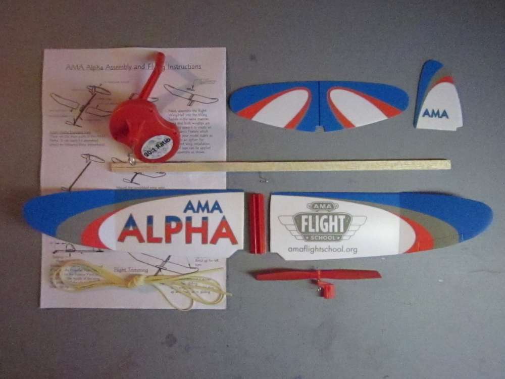
This is what you get.
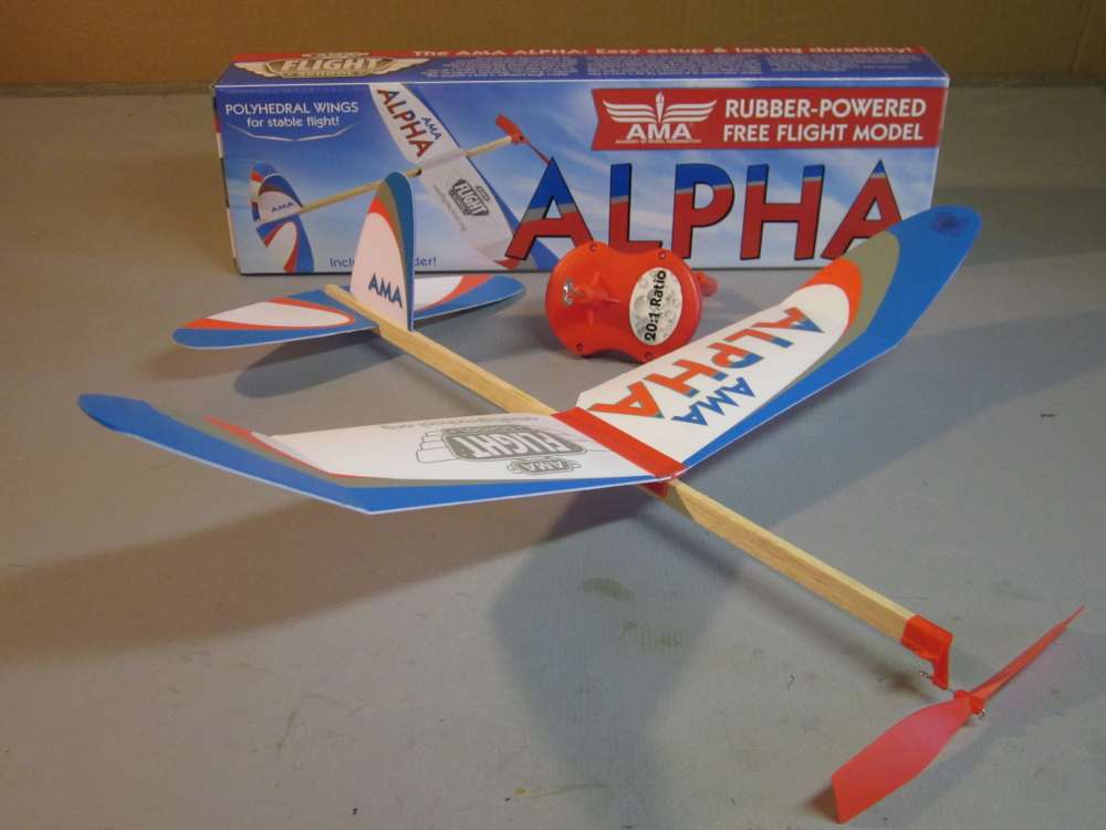
- Flat wing semispan 9 7/16″, full span 18 7/8″, maximum chord 3″. Aerodynamically favored elliptical wing planform.
- Wing area 47.53 square inches, determined by tracing the wing outline on thin cardboard, cutting it out and weighing the pattern.
- Prop diameter 5 11/32″.
- Stick 3/16″ x 3/8″ x 14 7/8″, 9# balsa, slotted for fin and stab, motor hook pre installed.
- 75 3/4″ of 0.0449″ x 0.0925″ Tan rubber weighing 4.5 grams. This is enough for about three 12″ motors or two 16″ motors. After you wear them out, you can get more standard 3/32″ or 1/8″ rubber strip from several suppliers.
- 20:1 winder. (This alone is worth the price of the kit.)
- Wing is cambered except at root, where it inserts into a North Pacific type straight clip. The root is reinforced with a metal tab.
- Full set of bendable control surfaces; elevator, rudder, ailerons.
- Parts weight without rubber is about 15.4 grams. Weight will vary as the density and weight of the balsa stick will vary.
The Winder
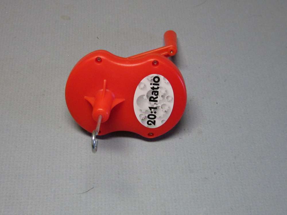
The 20:1 winder makes it easy to get the many turns into the rubber motor necessary for long flights. It is a little bigger than the familiar K&P winders; 3″ tall and 2 1/4″ wide. Side indentations allow a good grip, even with slippery lube on your fingers.
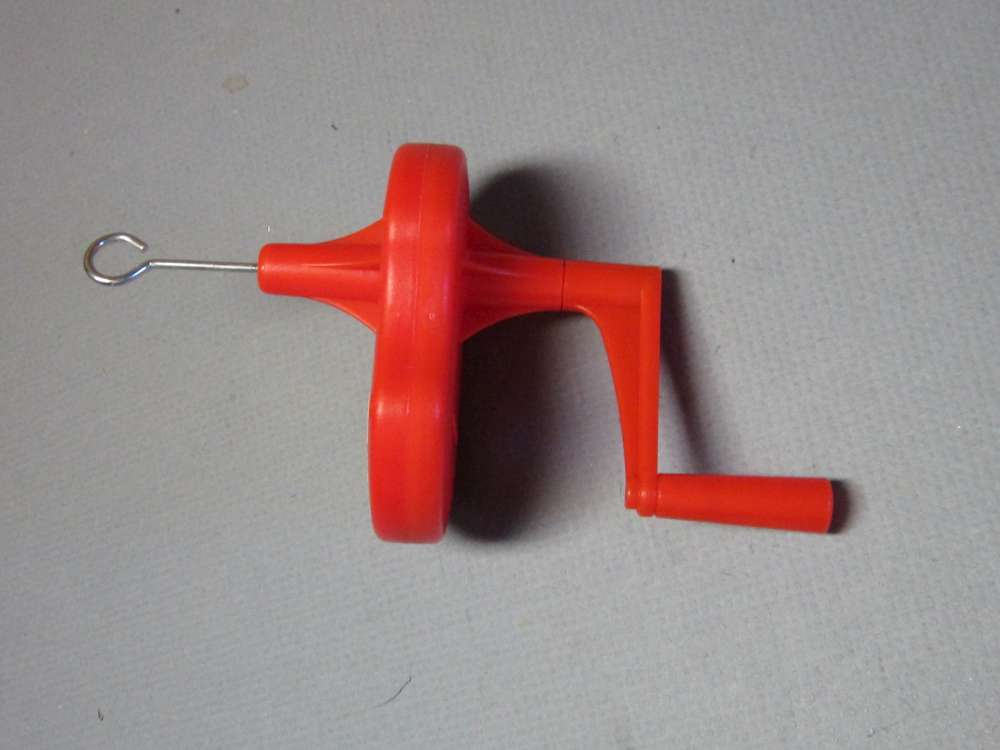
Hook material is 0.0785″ diameter. K&P is 0.047″
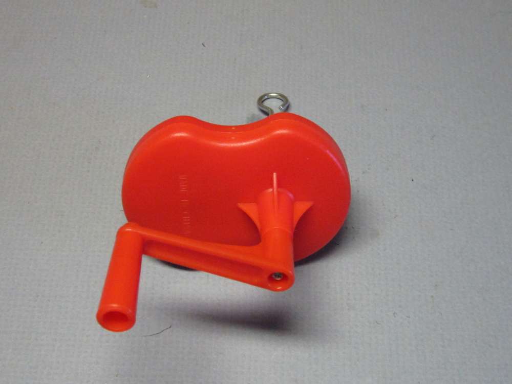
Made in China.
The Instructions
The assembly and flying instructions are clear and simple.


After reading them, it took me 59 seconds to assemble the plane, less motor.
Rubber Motor
Beginners might be at a loss on the instruction to lubricate the motor. Also, I recommend using an O-ring in the motor to make it easier to get it onto the hook when it is fully wound. You can learn what you need to know about making and preparing motors HERE.
Propeller Bearing
The propeller bearing box is unusual in that it has hooks on either side to engage a stooge. The stooge will hold the propeller end of the plane while you wind the motor from the back end. The instruction sheet shows a stooge made with what look like box nails. I suggest you use finishing nails or cut the heads off and file the cut ends round. The heads of the box nail will prevent you from getting the bearing box on or off the stooge. The nails should be 11/32″ apart on centers and a diameter that is a comfortable fit in the hooks, no bigger than about 1/16″.
I have found that the bearing boxes are a very tight fit on the stick. They are very hard to get on and off. The stooge hooks on either side of the bearing make it difficult to grip when you want to take it off and store the disassembled plane in its box. I found three things that help get the bearing off the end of the stick.
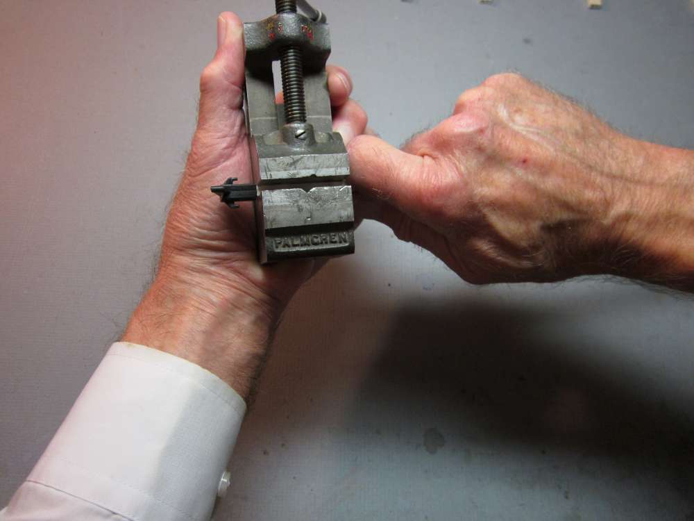
I put the stick in a machinists vise with a loose fit and pull the stick out.
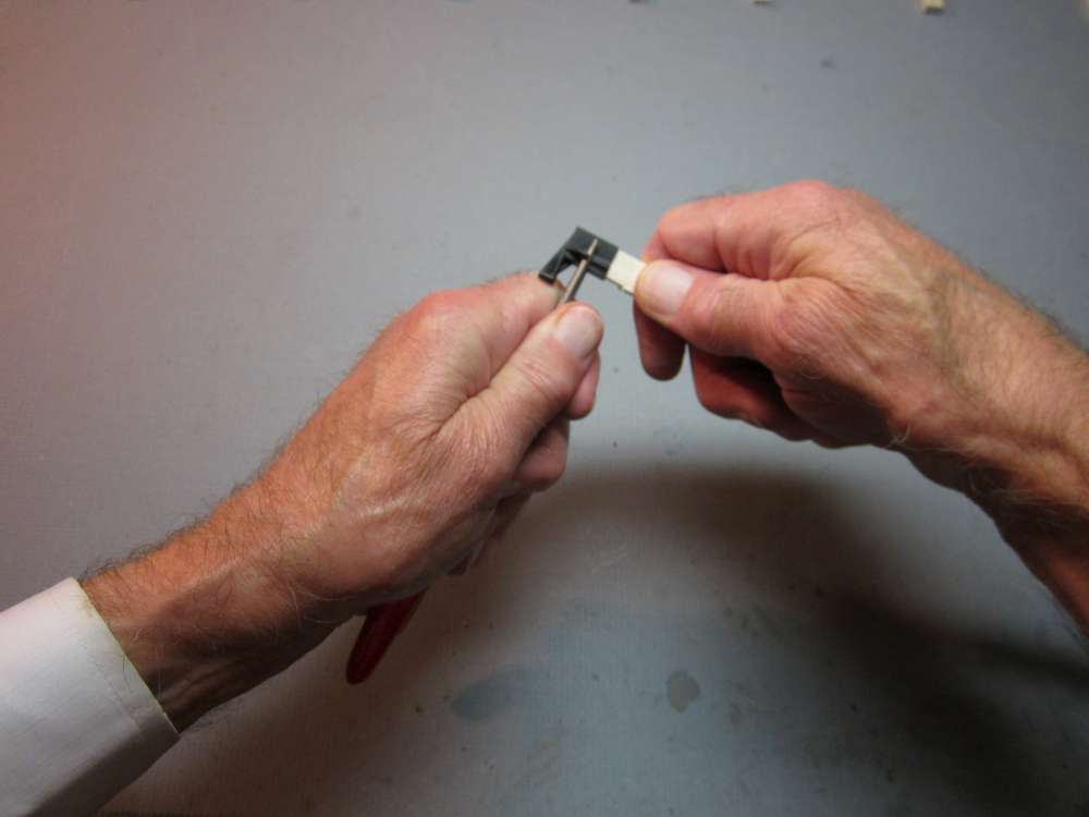
I put the pointed ends of needle nose pliers in the hooks and pull the bearing off.
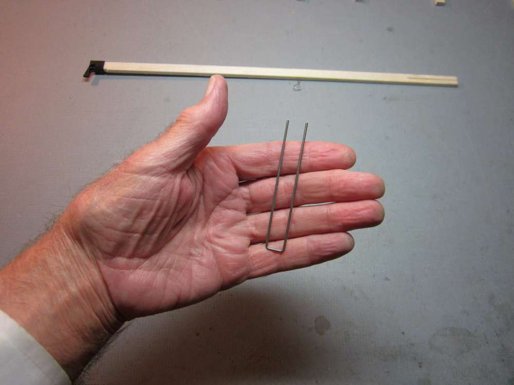
I made a wire tool from 0.055″ steel wire. You can get steel wire from your local hobby shop or online. It is 3″ long and 13/32″ wide between centers.
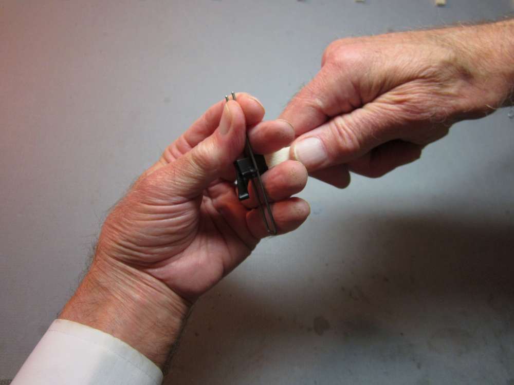
The wires are put through the hooks and the bearing is pulled off the stick.
Unpacking Your AMA Alpha
We will start with opening the box, in my usual step-by-step style. I know, you kids will already have the parts strewn all over the floor before I am done reading this.
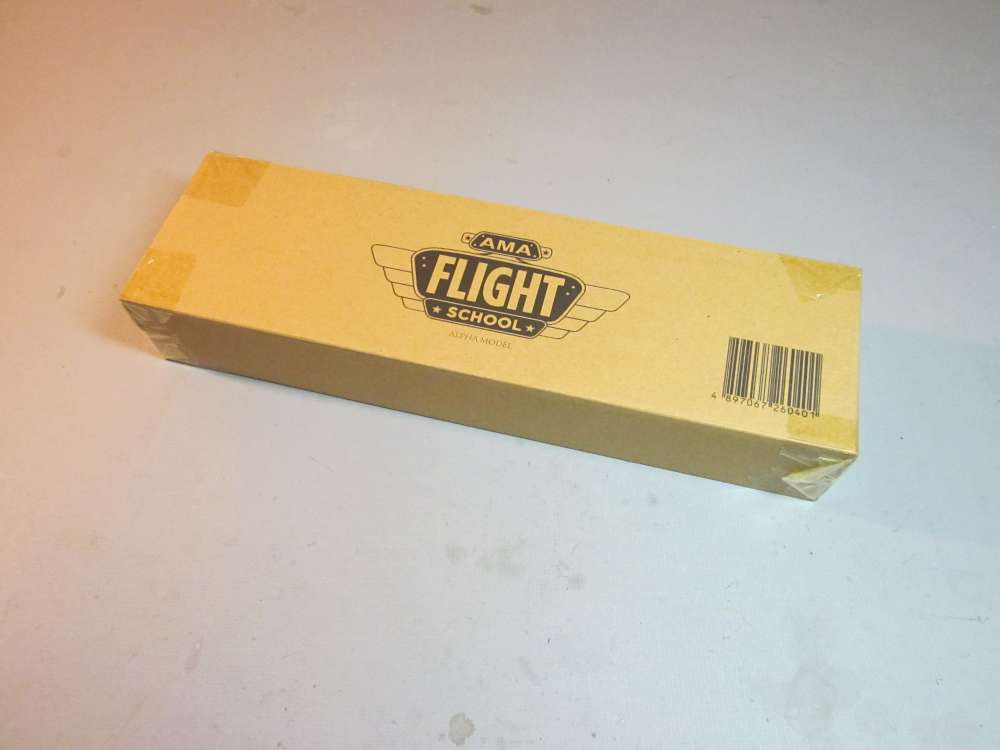
It comes well protected in a sturdy corrugated cardboard box.
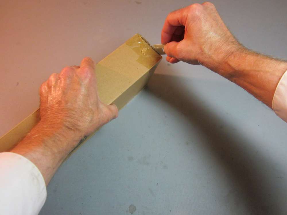
Cut the clear packaging tape across the end and along the edges.
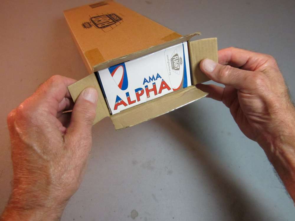
Open the ends to reveal the colorful and sturdy inner box that can be used to safely store your AMA Alpha when not in use.

Withdraw the inner box. Note the Polyhedral Wings picture in the upper left corner. Open this box carefully to preserve it. One feature of the AMA Alpha is that it comes apart and the parts can be safely stored in this box.
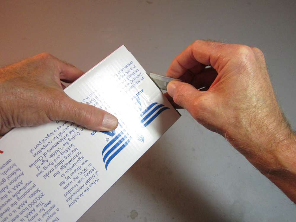
Cut the clear tape that covers the tab.
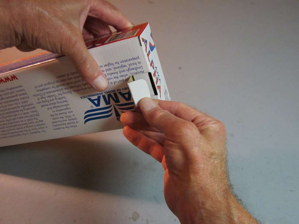
Pull the tab out.
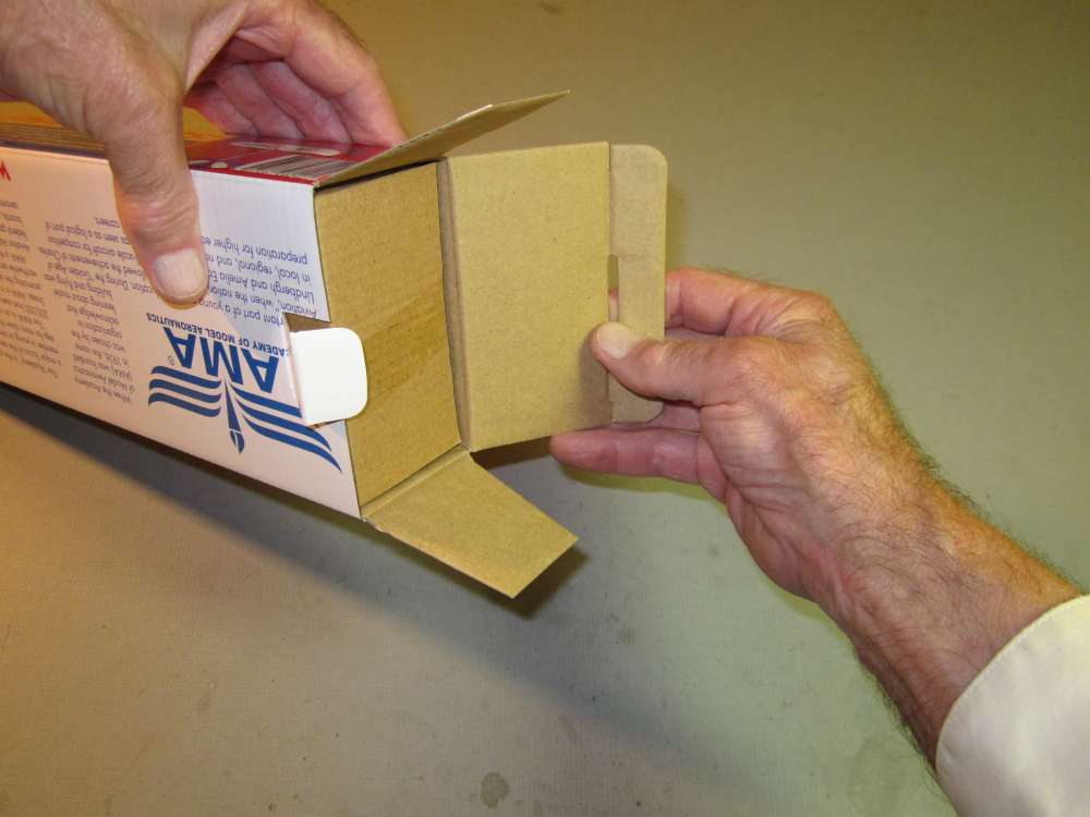
Open the end and pull out the flaps, exposing the inner tray.
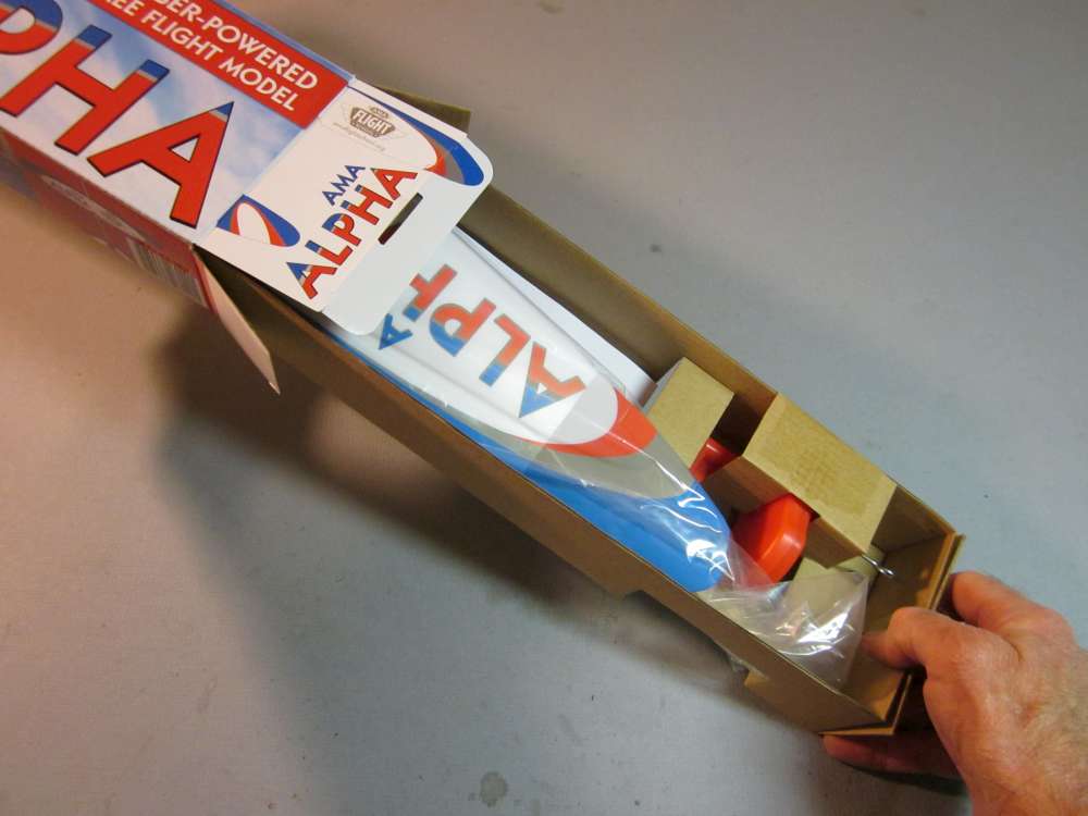
Pull out the inner tray.
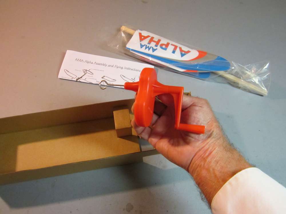
Take everything out of the tray.
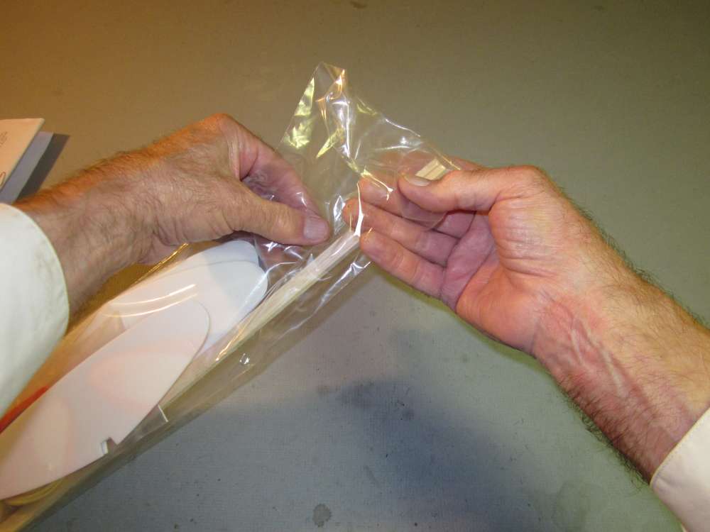
The poly bag of parts is folded over and taped down. The best way to open it is to slide a finger under the folded end of the bag and peel the tape up off the main body of the bag. Don’t grip the bag with the fragile foam parts inside.
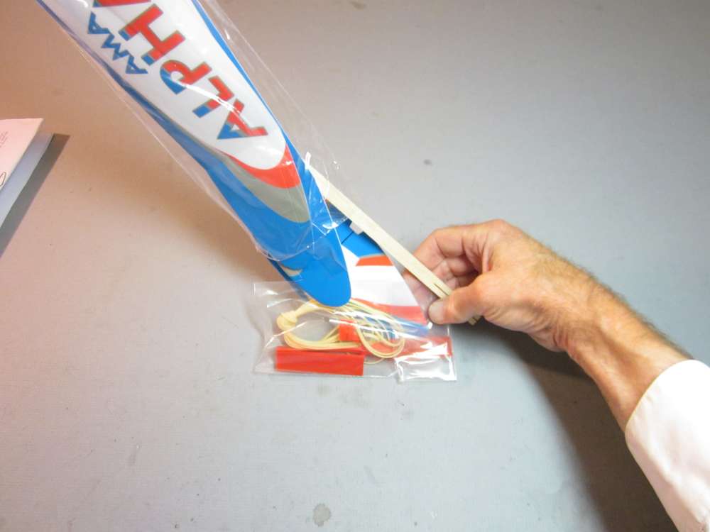
Hold the sticky part of the tape away from the parts as you dump them out.
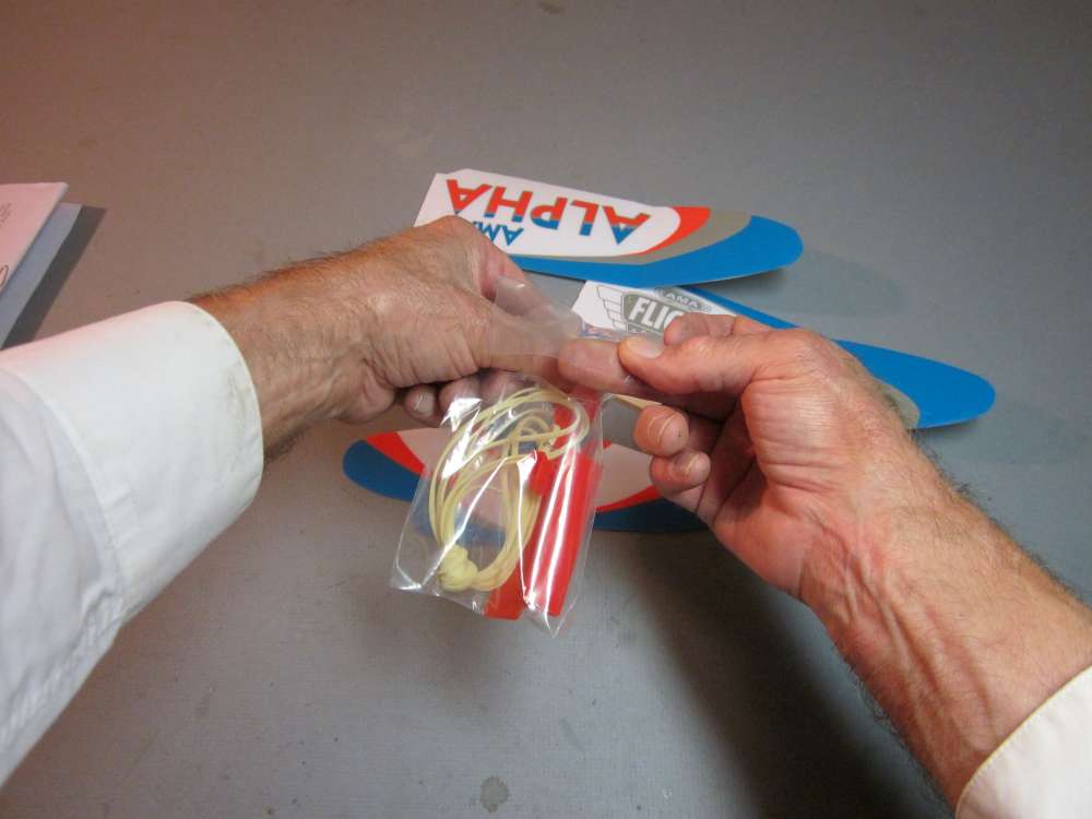
Do the same with the inner bag, containing your AMA Alpha power plant and wing clip.
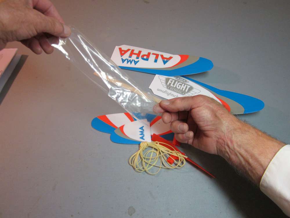
Dump the parts out onto your table.
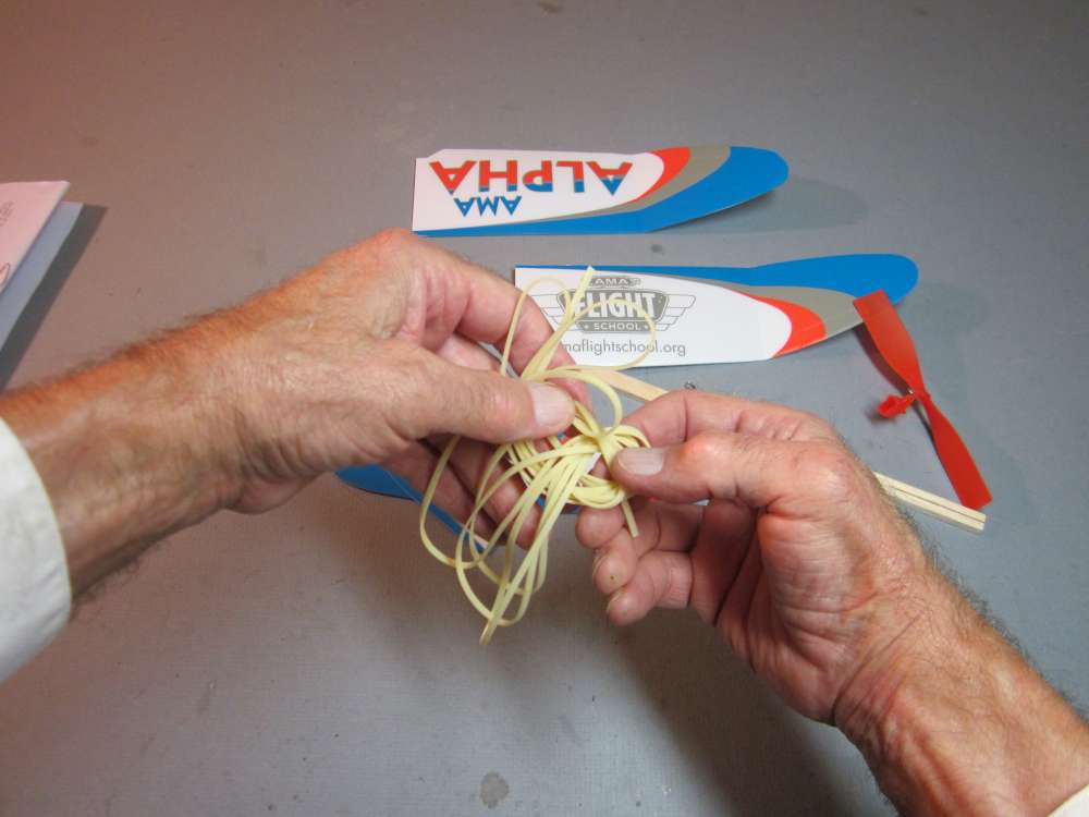
Untie the skein of rubber. Tension in rubber promotes oxidation. Rubber should be protected from sunlight. You may put it back in the bag and into the box until you need it.
This completes the longest and most difficult part of assembling your AMA Alpha.
Measuring Areas
At this point, I wanted to measure the area of the wings. You don’t need to do this, but you might like to know how I did it. Some of you may be using these numbers in future lessons. (Tail Volume Coefficient and Aerodynamic Coefficients.) It is a good method to know about for other airplanes, as well.
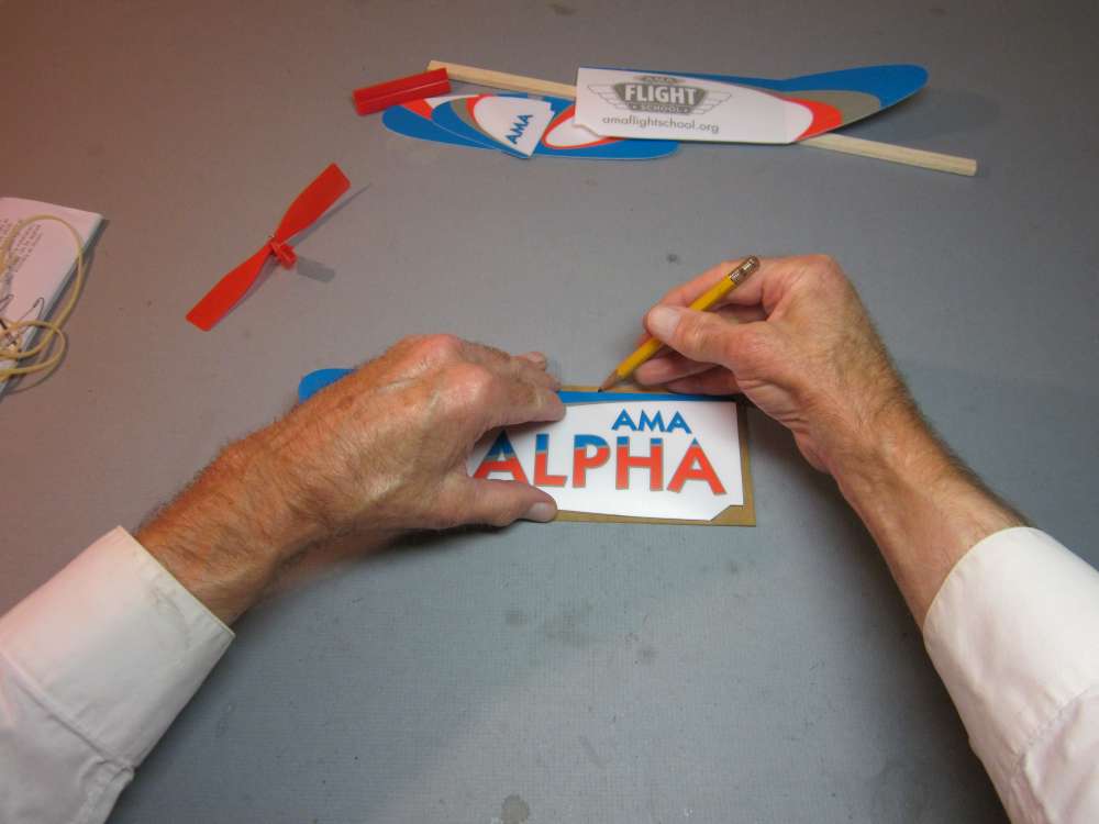
I cut out a 3 1/4″ x 9 3/4″ rectangle of thin cardboard, just large enough to contain the shape of the wing. It has 31.6875 square inches of area and it weighed 10.6383 grams (I am keeping an absurd number of decimal places because that is what we get when we multiply fractional inches). I put the wing on top of the cardboard and traced around the perimeter with a pencil, being careful to not crush the wing.
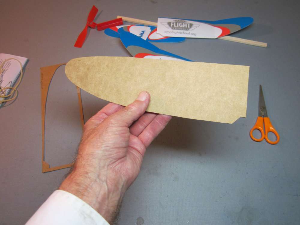
I cut out the wing pattern and weighed it. It weighed 7.9787 grams. The areas are in proportion to the weights, so the area of our half wing pattern is 31.6875 x (7.9787 /10.6383) = 23.7656 square inches. The area of two wing panels is then 47.53 square inches (rounding off the final number to a more reasonable two decimal places at the end.)
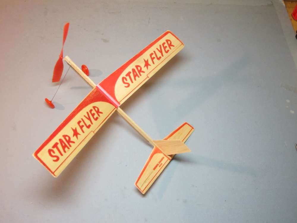
This is important because the required propeller size depends on the area of the wing. There is a relation between the area of the wing that supports the airplane’s weight and the area of the swept disk of the propeller that pulls it through the air. As a rule of thumb, the propeller diameter should not be less than about the square root of the wing area and as much as 1.5 times the square root of the wing area. That suggests our propeller should be 7″ to 10″ in diameter. It is noteworthy that the North Pacific Star Flyer, with a similar wing area, has a 7″ prop.
I also cut out a 3″ x 11″ rectangle of cardboard to find the areas of the fin, 5.0459 square inches, and tailplane, 14.2053 square inches. This last will be used to calculate a Tail Volume Coefficient, an index of longitudinal stability, to be explained in another post.
Assembling Your AMA Alpha
The instructions are quite good. There are a couple things to watch out for when assembling your AMA Alpha.
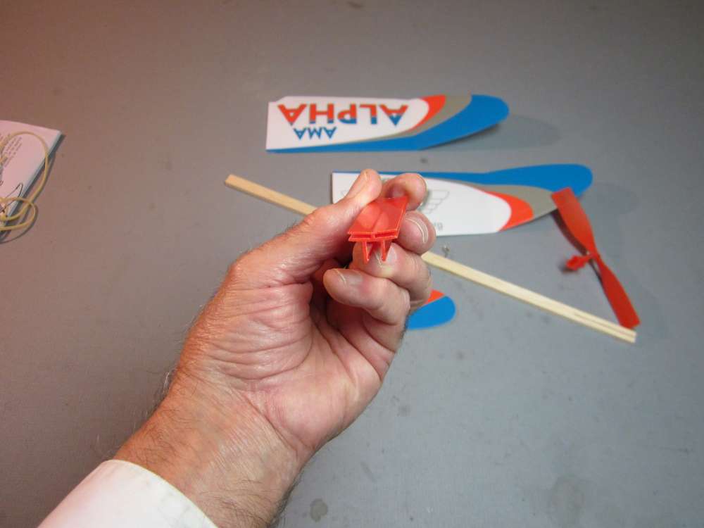
Start by examining and becoming familiar with all the parts. They are clearly identified on the instruction sheet. Except the wing clip, or saddle. The North Pacific wing clip was the subject of their Patent No. 2,739,414.
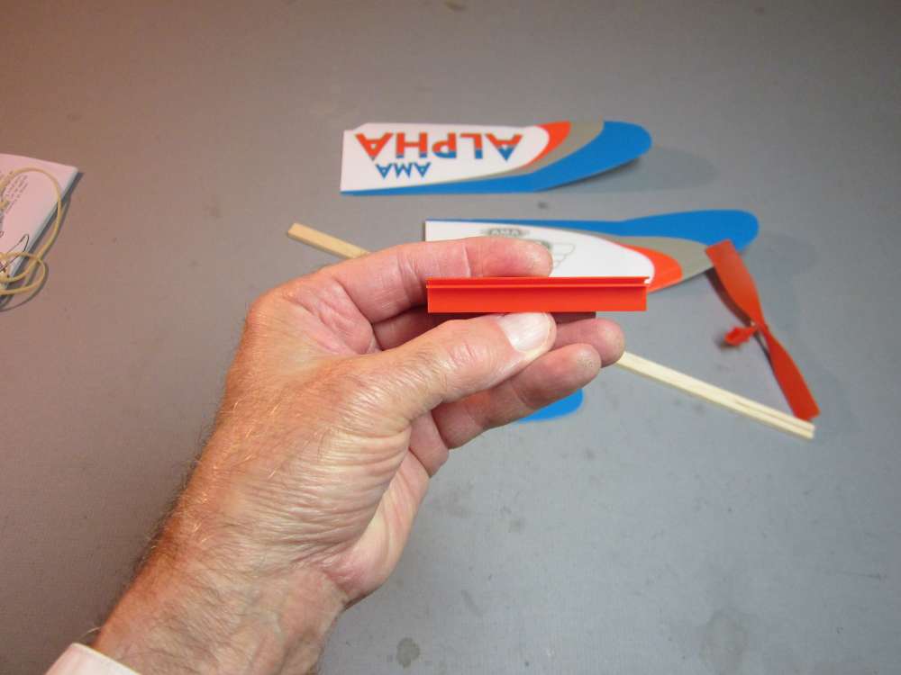
The wings are pressed into the two side slots first and then the wide slot goes over the stick. The stick presses against the two side plates, which in turn tighten the grip on the wings. It is important that the parts be assembled in that sequence, otherwise the wing roots can be damaged.
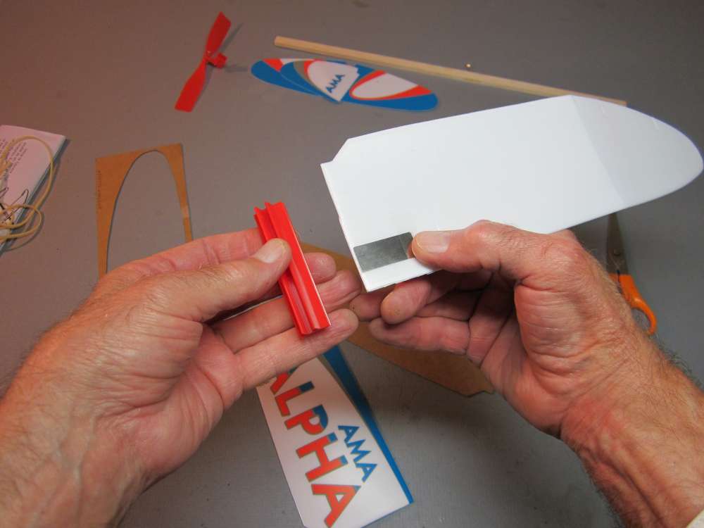
This is complicated slightly on the AMA Alpha because the foam wings are reinforced at the roots with a metal plate. This plate sticks up a wee bit above the surface of the foam and can interfere with insertion of the wing into the slot.
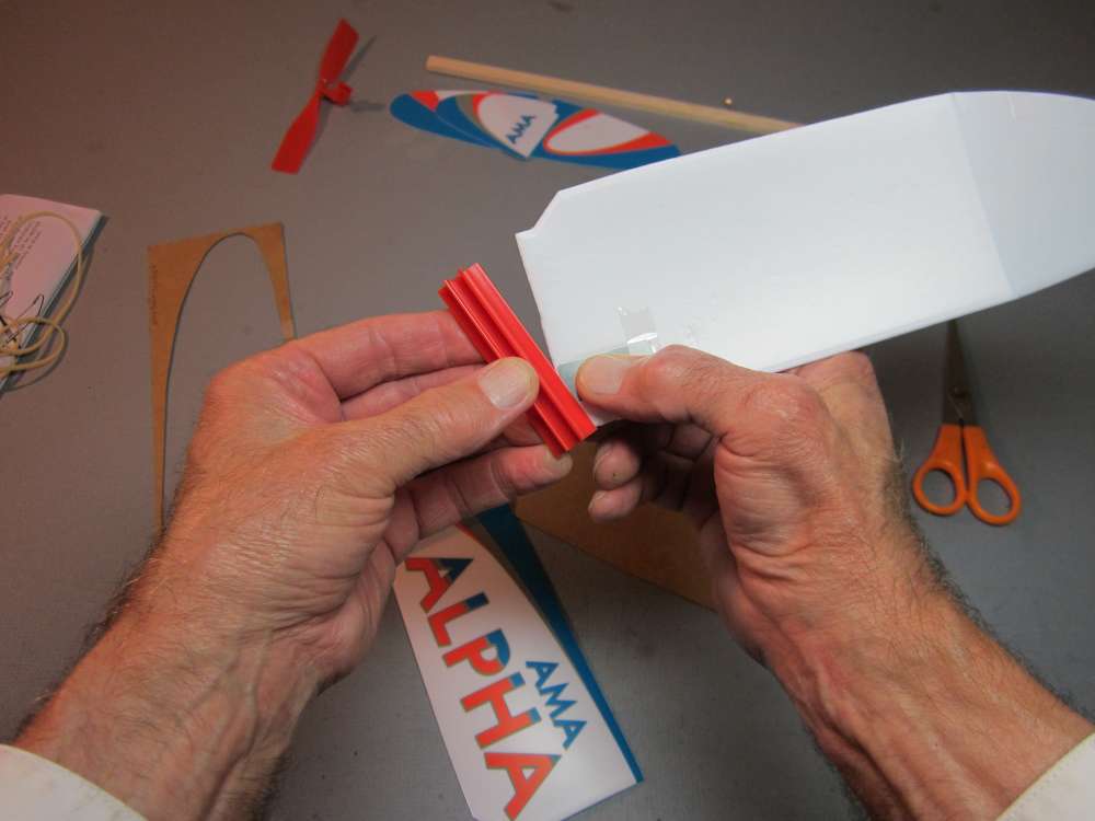
Grip the plate, insert the leading edge corner into the slot and rotate the plate and wing into the slot. If you try to insert just the foam wing root into the slot, the metal tab can catch on the edge of the wing clip. You must insert it so the metal plate goes into the slot.
After doing this a few times I found that it works better to start by inserting the trailing edge corner into the slot and rotating the wing root down into the slot, being careful that the metal tab goes into the slot.
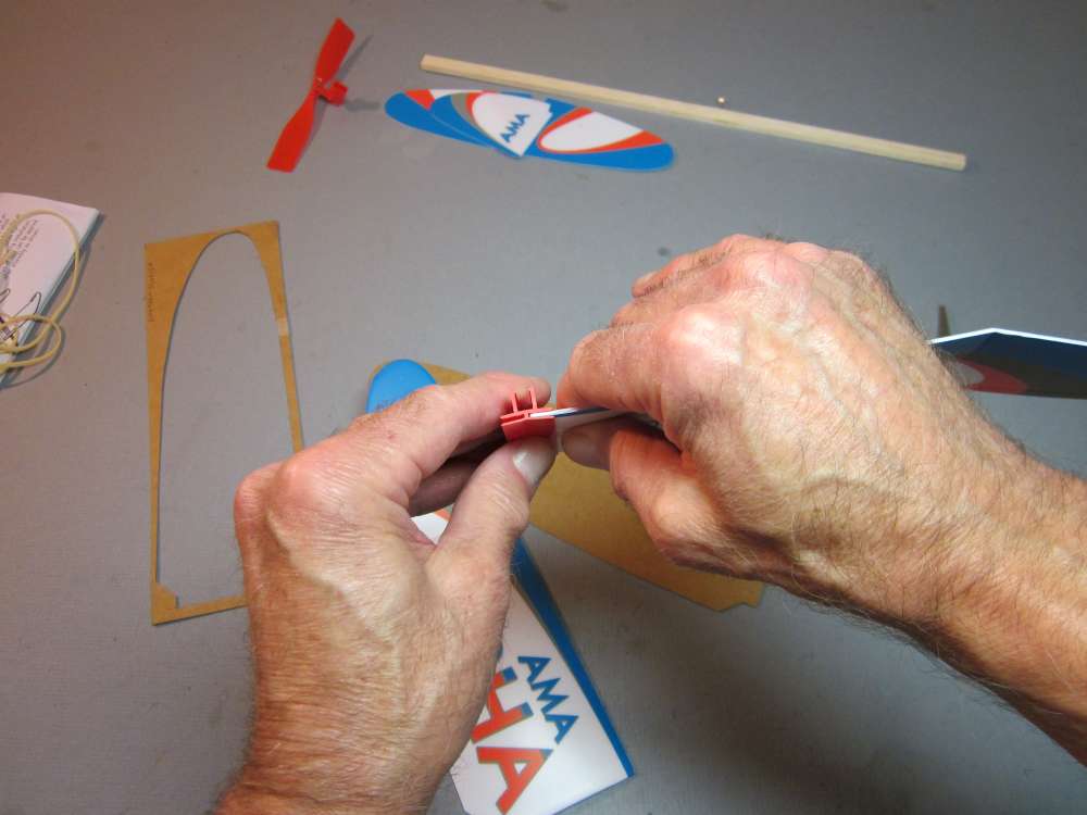
Grip the wing close to the end and press it all the way into the slot, front and back. Make sure there is no gap between the end of the wing and the base of the slot on either end of the wing root.

Insert the other wing in the same way. Hmmm. What happened to that elegant polyhedral wing shown on the box?
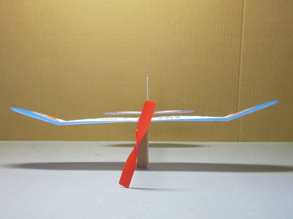
Notice the wing does not have any central dihedral, as shown on the little polyhedral diagram on the front of the box. It goes straight across the center line. This is not per the original design, shown in early publicity pictures. Your plane will fly under power like this, but not as well as with full dihedral and I want to do glide testing before powering up. I found that without the central dihedral, the glider has a spiral dive, also known as a yaw divergence; once it starts to turn to either side, the turn tightens, the bank steepens and ends in a dive. It will not fly in a straight line. What happens is that when the plane banks to either side, it sideslips. The sideslip produces an airflow against the side of fin. That causes the plane to turn downward toward the low wing. That brings the nose down into a steeper dive. If there isn’t enough dihedral to counter the sideslip and reverse the bank, the unstable motion accelerates. There is no trim or control cure for this, bending the rudder will simply give it a preference for crashing in one direction more than the other.
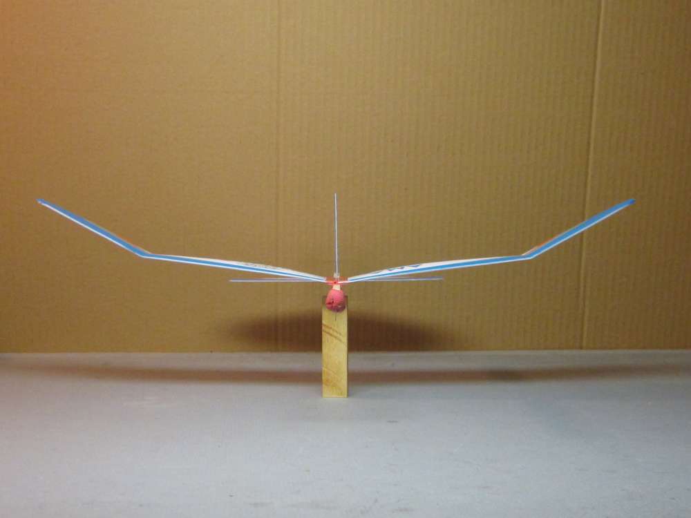
Increasing dihedral fixed the problem. Reducing fin area also may help. Under power, the propeller reduces the effect of the fin. The fin area looks about right. It does not need to be changed. I decided to fix the dihedral.
I have noticed in videos of AMA Alphas flying under power that they also bank excessively to the left, side slipping downward, losing energy and altitude. With proper central dihedral, the plane climbs and flys better.
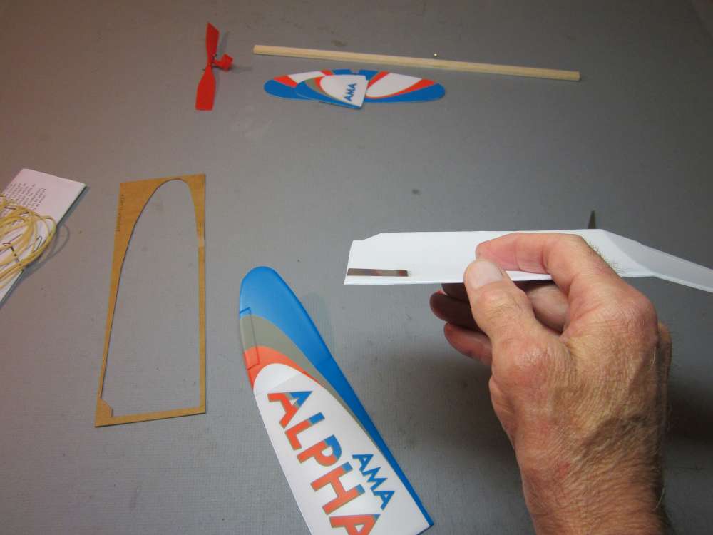
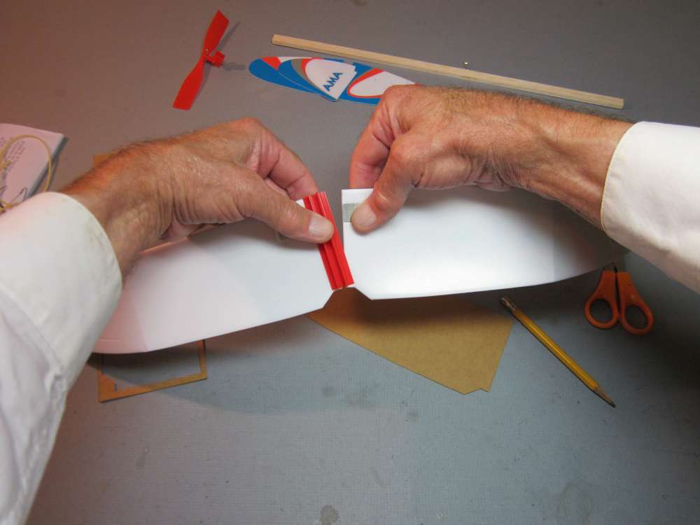
The problem is caused by the metal tabs which were added to strengthen the flat wig root. The tabs extend up into the cambered part of the wing panel, placing them at an angle to the plane of the wings. Dihedral can be returned to the original design amount by bending the metal tabs.
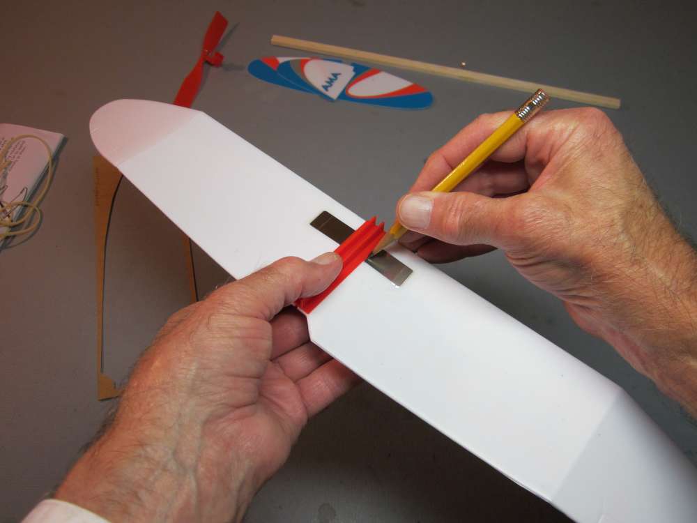
With both wings pressed firmly into the slots, run a pencil along the edge of the clip to mark on the metal tabs.
Remove the wings from the clips.
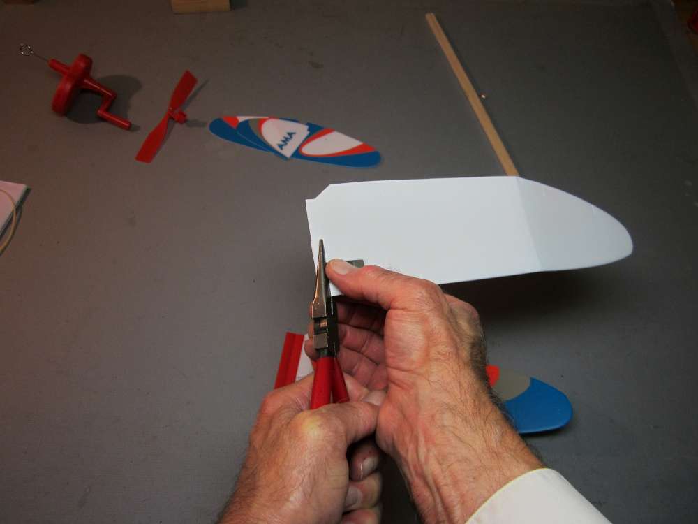
Grip the wing with your pliers, lining up the straight edge of the pliers with the pencil line.
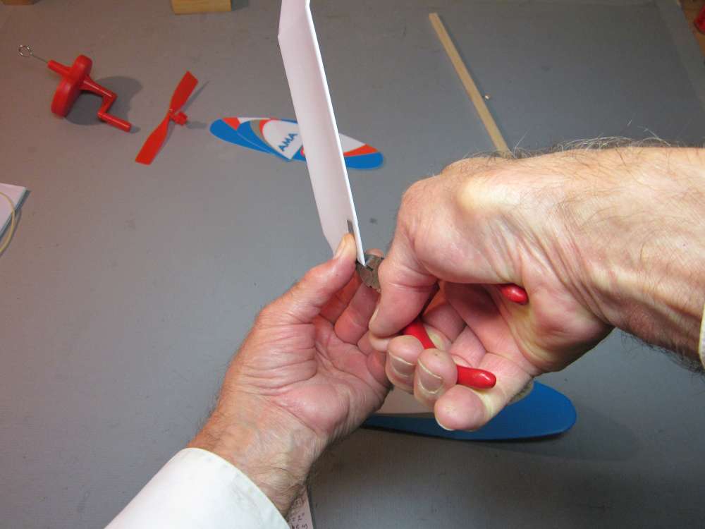
Bend the metal clip. It must be bent quite a bit more than just the amount you want because the metal springs back quite a bit after releasing the grip. It took quite a bit of bending, about 60 degrees of deflection. Go at it gradually. You can bend it back if you overdo it. Keep at it until it looks right.
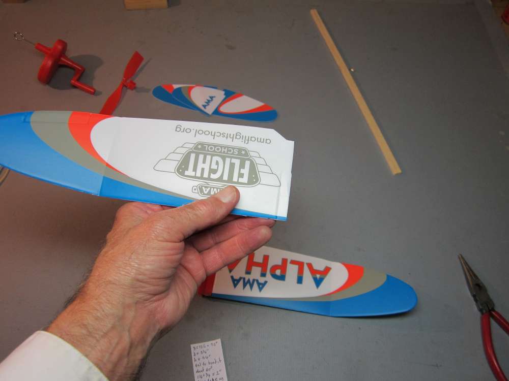
This will put a crease in the top of the wing.
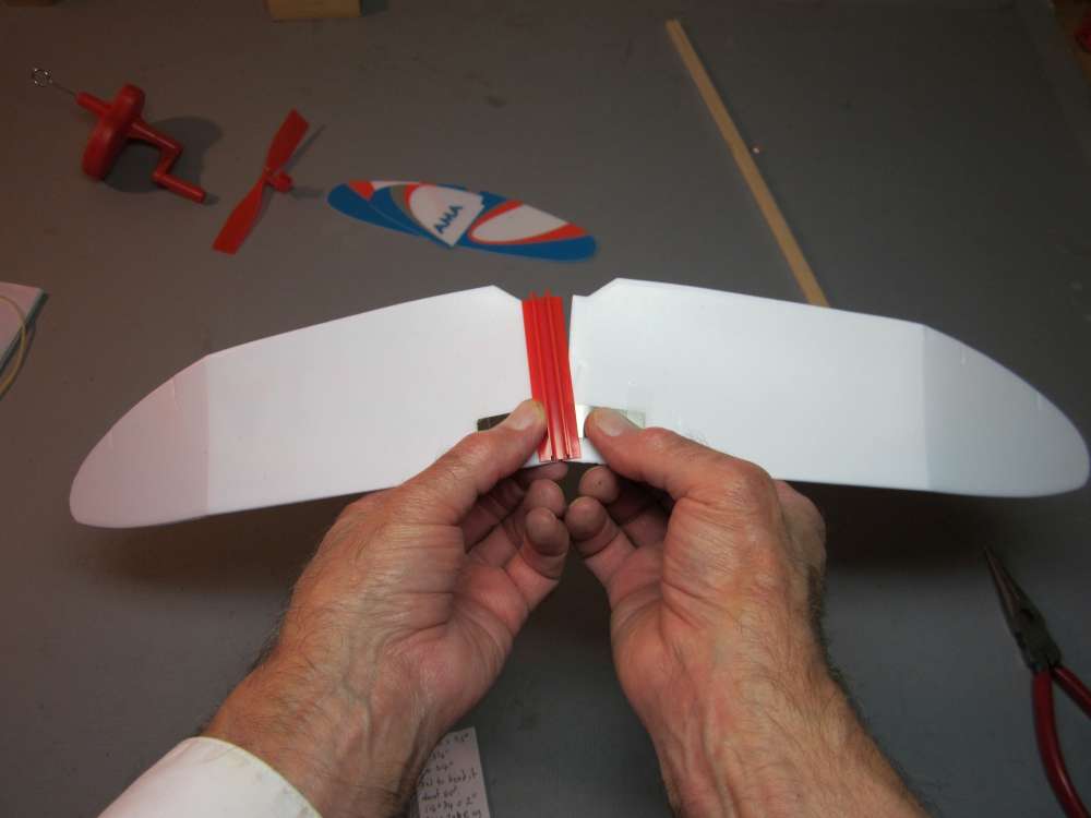
Put the wings back in their slots.
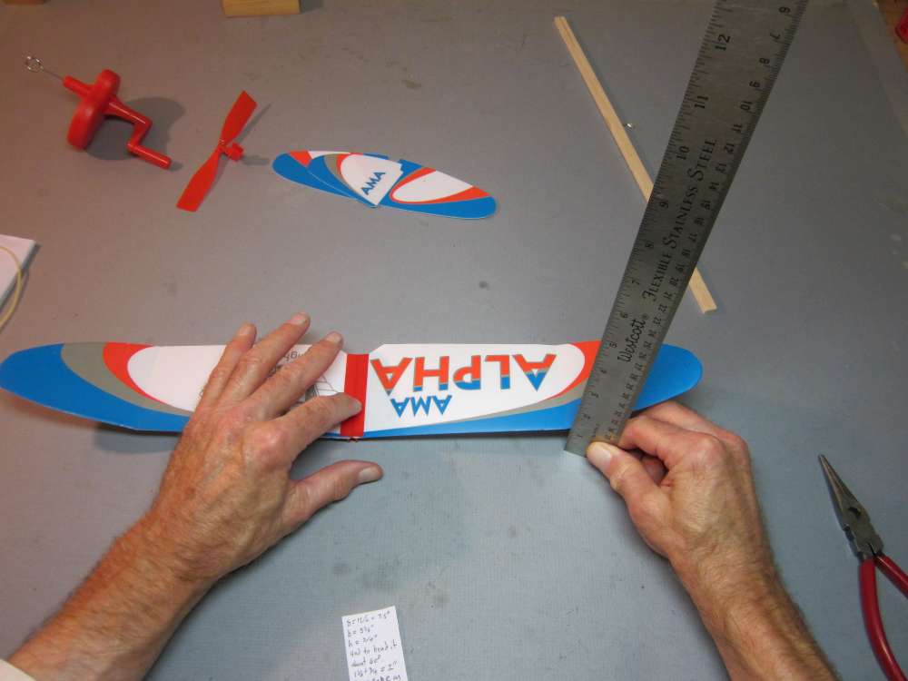
Press the wing clip flat on the table top and measure the height of the wing at the dihedral break line. It should be 1 1/16″ to match the angle shown on the box cover. Both wings should be the same. That completes the wing assembly.
Dihedral Bending Jigs
Using pliers might be alright if you are fixing the wing tabs on only one AMA Alpha, but if you are preparing two dozen of them for a class, this gets tedious. We need a specialized tool to make the work fast and accurate.
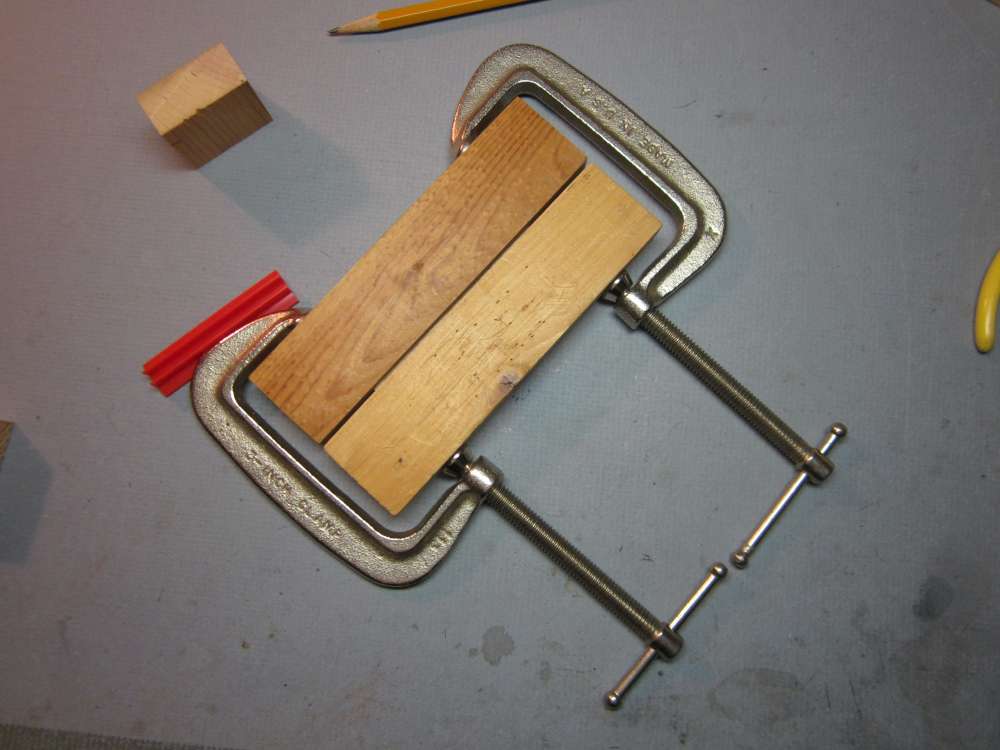
I cut a 7/16″ x 3 1/2″ piece of hard 1/16″ balsa and put it between two 3/4″ x 1 1/2″ x 6″ pieces of pine and clamped it all together to form a 5/16″ deep slot. This worked well, so I made a more permanent jig.
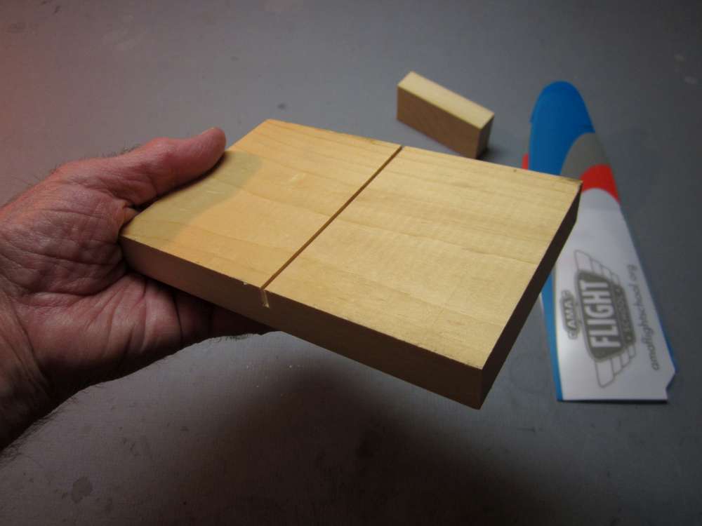
I cut a 4″ x 6 1/16″ block from 3/4″ pine and cut a 1/16″ wide saw kerf 5/16″ deep across the middle.

I insert the wing root into the slot, starting at the trailing edge.
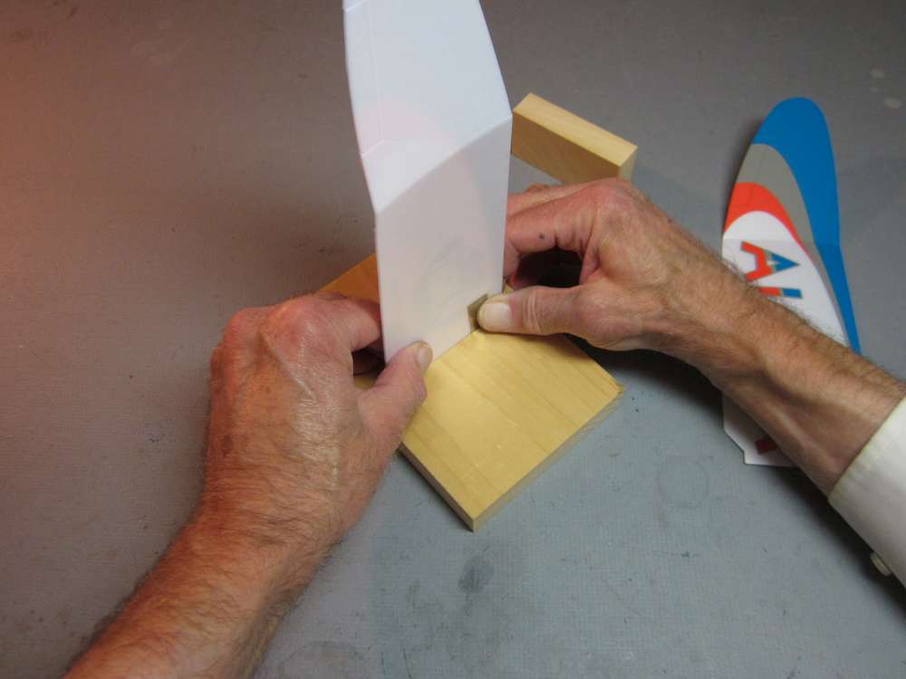
I rotate it into the bottom of the slot, being careful to get the metal tab into the slot.
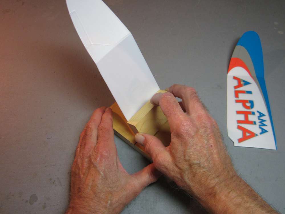
I place a 3/4″ x 1 1/2″ x 3″ block against the base and the wing.
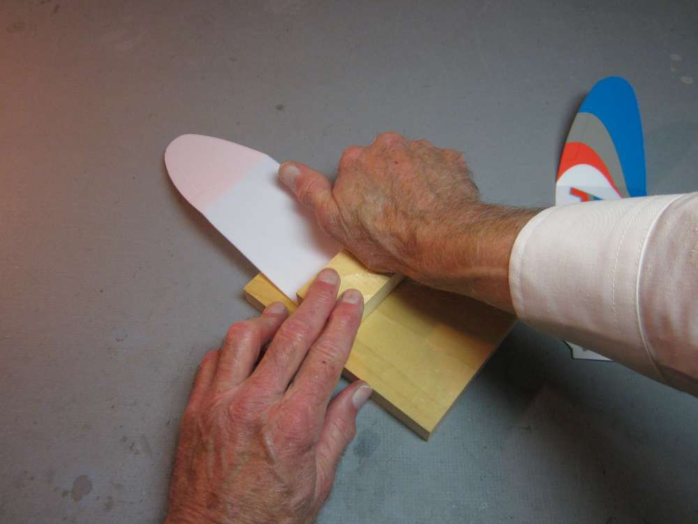
I rotate the block to press the wing firmly flat against the base. It does not need to be pressed hard. A couple trials will show you how hard to press it.
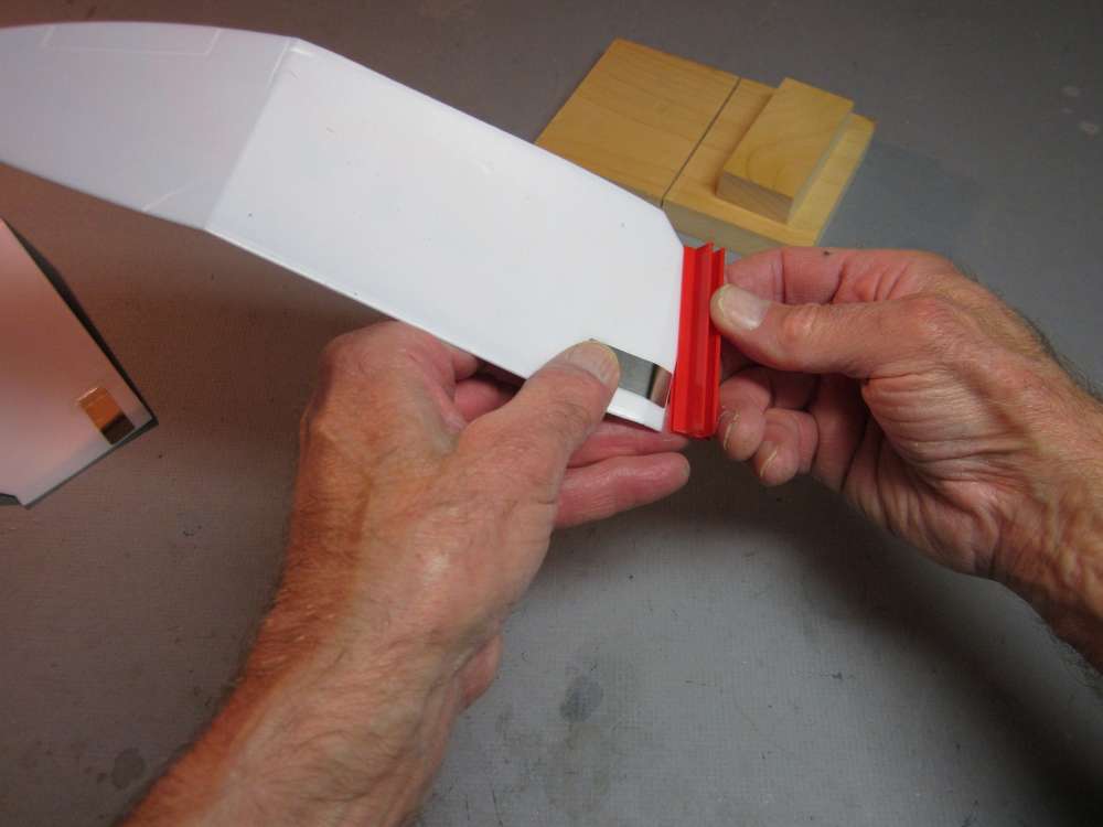
Insert the wing into the wing clip, starting with the trailing edge.
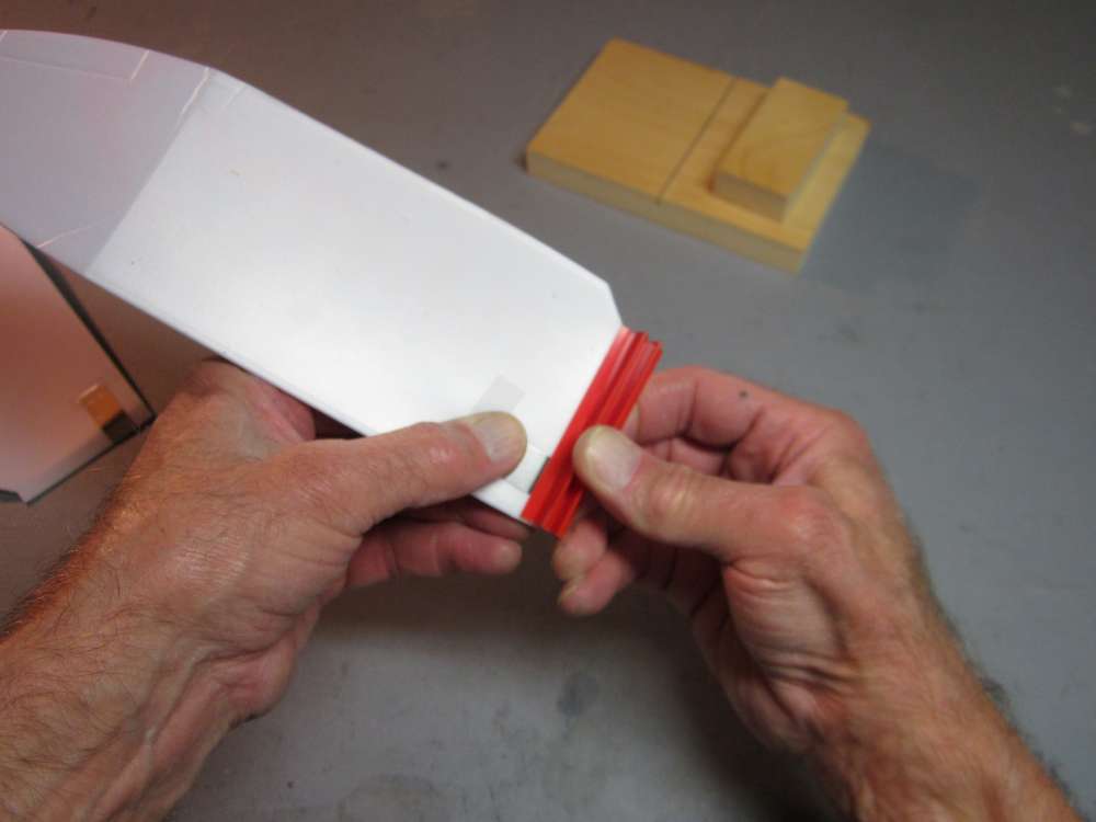
Rotate it down so the metal tab goes smoothly into the slot and the root is firmly seated along its entire length.
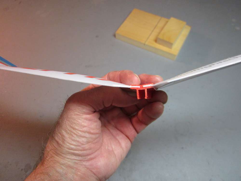
Do the same with the other wing.
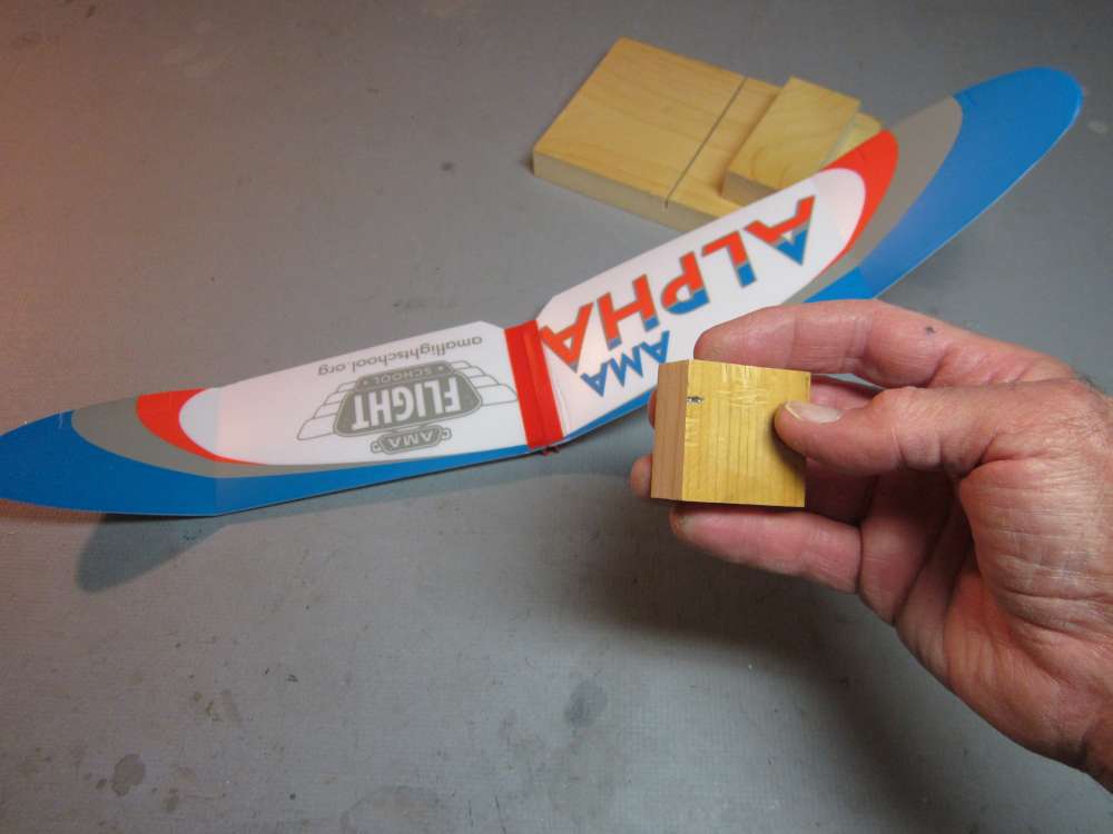
Rather than use a ruler to measure the height off the table, I put a mark 1 1/16″ up along one edge of a wood block to serve as a gauge.
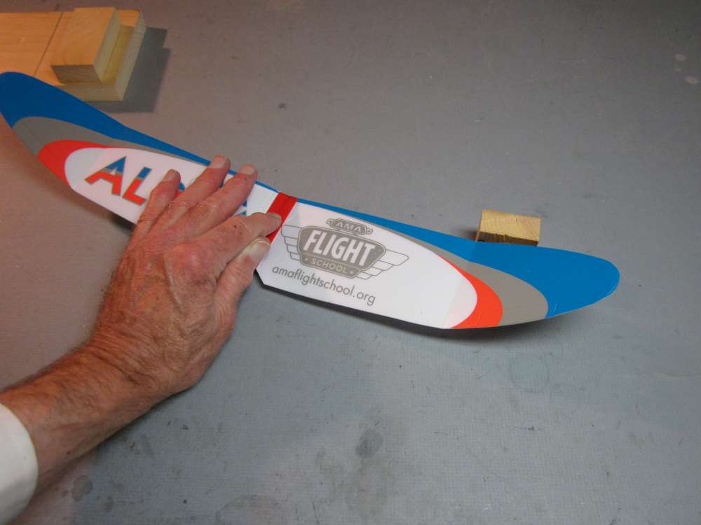
I press the wing clip firmly against the table top and check that the leading edge at the dihedral break is 1 1/16″ up from the top of the table. Minor adjustments may be made by bending the tab with the fingers.
Tape Wings

Later I put small tabs of painter’s tape on, front and back, to help hold the wing in place. This tape is not as sticky as masking tape, so you can peel it off without pulling chunks out of your foam wings.
Balance the Wings
I wanted to glide test the airplane to learn something of its aerodynamic qualities. To do that, I placed some clay on the nose equal in weight to the propeller assembly.
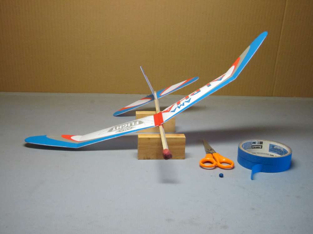
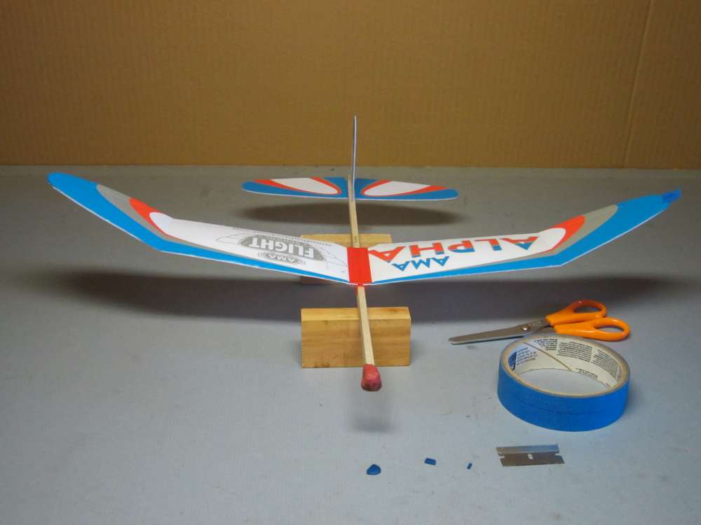
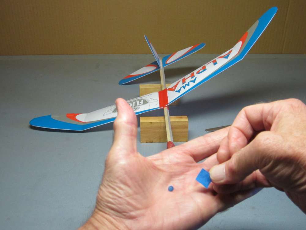
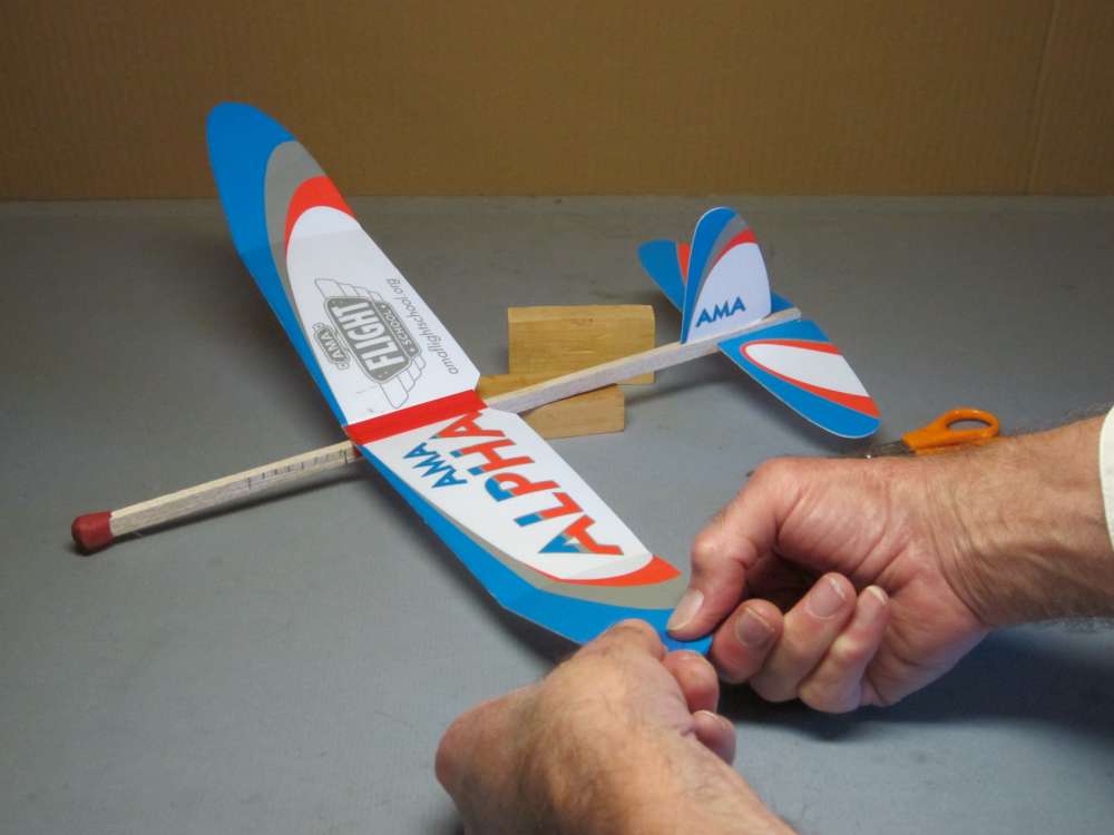
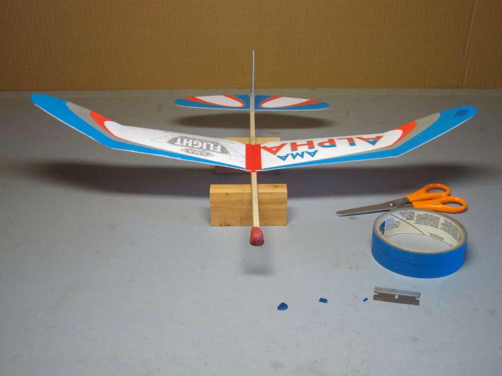
I found that, even with the proper dihedral, the AMA Alpha would not glide straight. Both the first two wanted to turn right. Neither would sit level on lateral supports. Both of the first two tilted to the right. The right wings were 0.1 and 0.2 gram heavier than the left wings. This is not good because an imbalance like this can make the plane turn to one side. If it turns in a direction you like, OK, but in this case a right turn was not desired. I placed the wings against each other and they were a perfect match, as far as I could tell. I checked the thickness of the wing tips with a micrometer, which is difficult on soft material, and they seemed to be the same. Perhaps the density of the foam is different. I considered sanding the heavy wing tip, but foam is light and I didn’t know how much would have to be taken off. I decided to balance the wings by adding a dab of ballasting clay to the light wing tip.
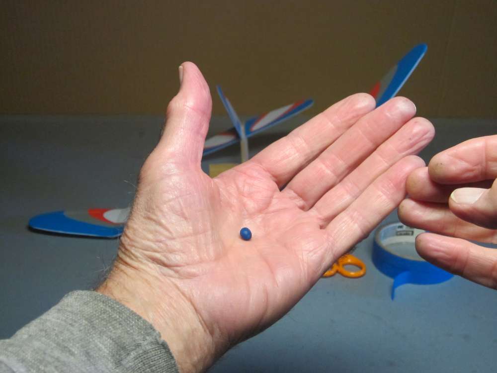
I started by kneading a pea size lump of clay to soften it and then rolling it into a ball.
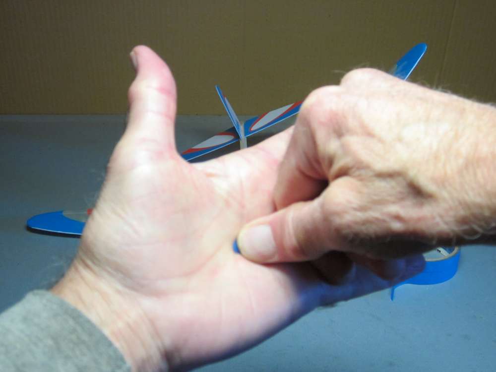
I squashed it flat.
I cut that in half and taped it to the left wing tip. That was too much.
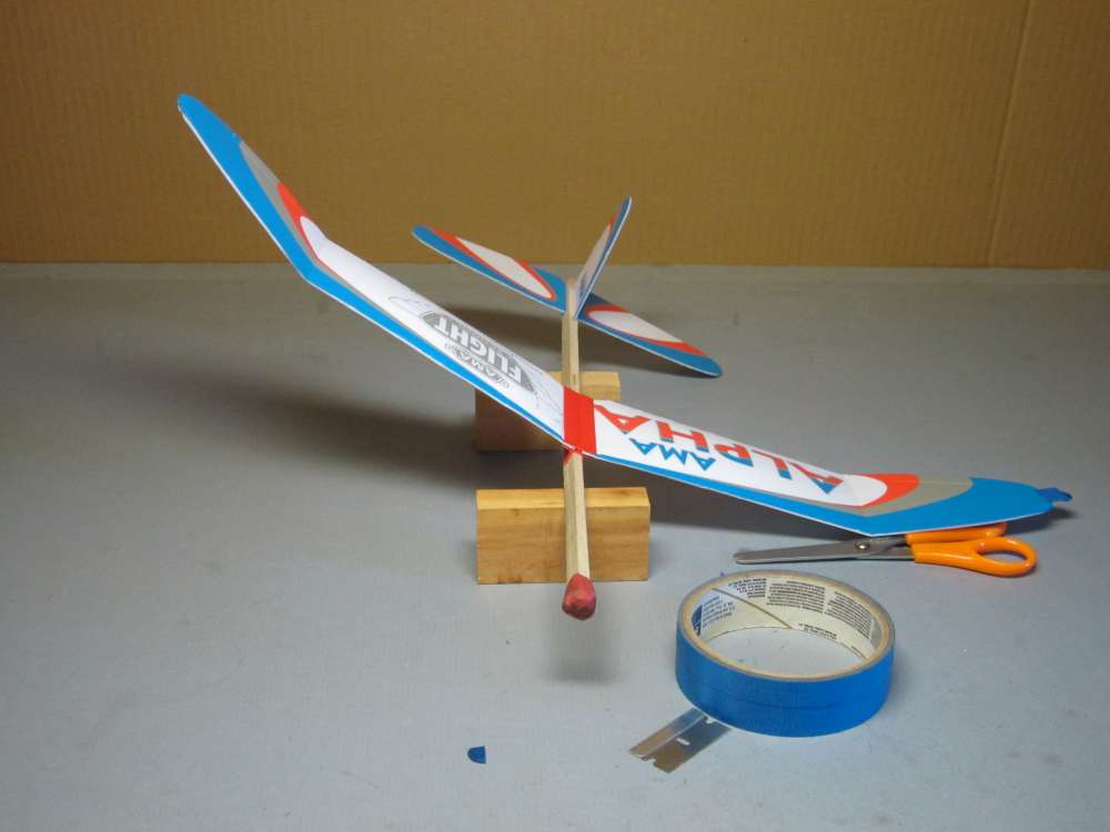
I kept cutting it in half until it balanced. I think it is about 0.05 gram.
I rolled that piece into a ball, squashed it flat and stuck it into the center of a piece of tape.
I stuck it down to the top of the wingtip. The blue blends in pretty well.
Now it balances nicely.
This is important because in the glide tests, the plane must fly in a perfectly straight line. Under power, the initial motor torque will bank a balanced plane left and it will fly in a left circle. In this case, with the right wing heavier, the plane might have flown straight ahead and come down circling to the right. With more torque it might have started out in a left circle, straightened and come down circling right. That kind of figure 8 flight path is hard to confine to a small flying field. We want consistent circles that will fit within our field, otherwise we will lose the plane. In weighing six pairs of wings, I found weights to vary from 2.4 to 2.8 grams. Right wings ranged from 2.4 to 2.8 and averaged 2.63 grams. Left wings ranged from 2.5 to 2.7 and averaged 2.57 grams. If you have multiple kits, weigh the wings and try to match left and right for weight. If you plan to fly your plane with high power climbs, you may want the plane to climb and descend in right turns, so a heavy right wing may be an advantage. This will allow a right descent without having to waste energy generating lift on a rudder.
Preparing for Powered Flight
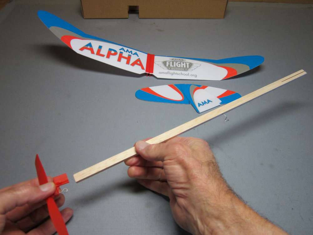
The stick fits into the propeller holder. Be sure the prop hook and motor hook are on the same side of the stick.
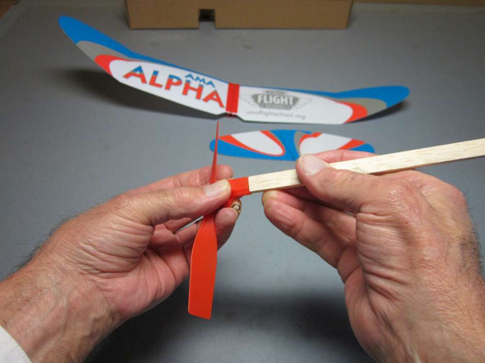
The stick is a little too big to fit easily into the propeller holder. This can make it difficult to get the stick in, especially for harder stick wood. You can sandpaper the stick faces to get it to fit.
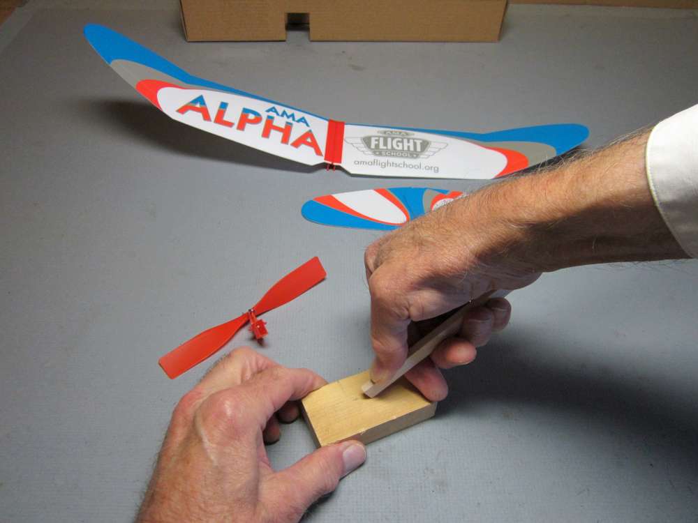
I found that by pressing the corners against a hard surface, I could taper the end of the stick.
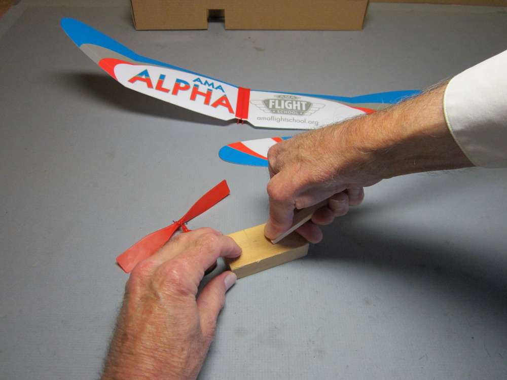
Get all four corners.
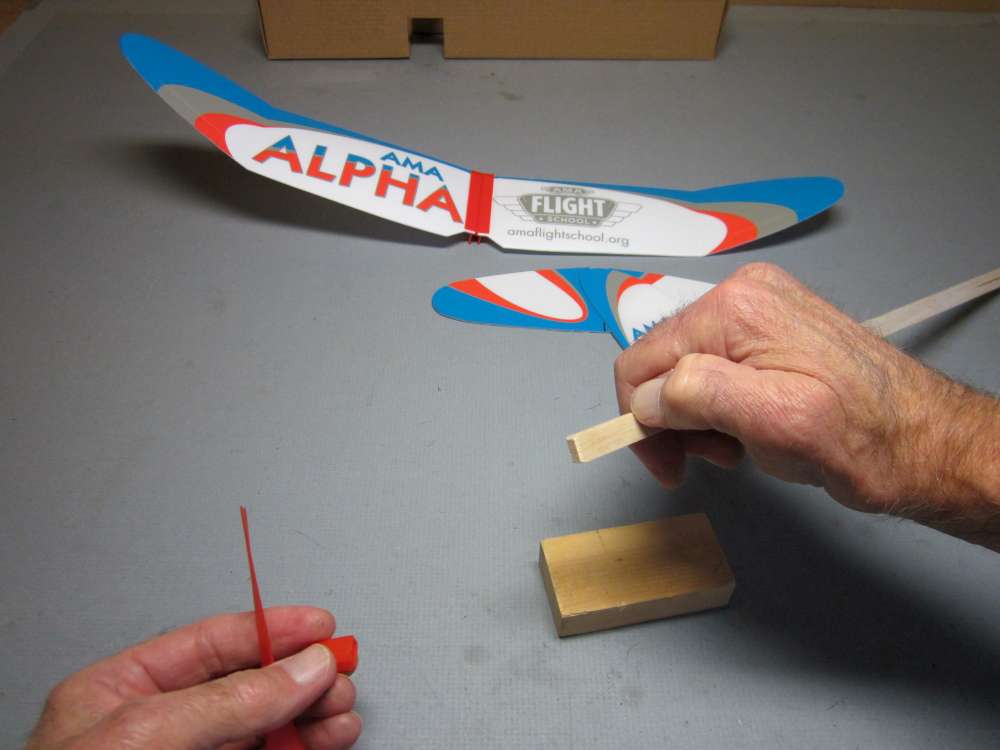
Grip the stick close to the end. Holding it farther away increases the risk of breakage.
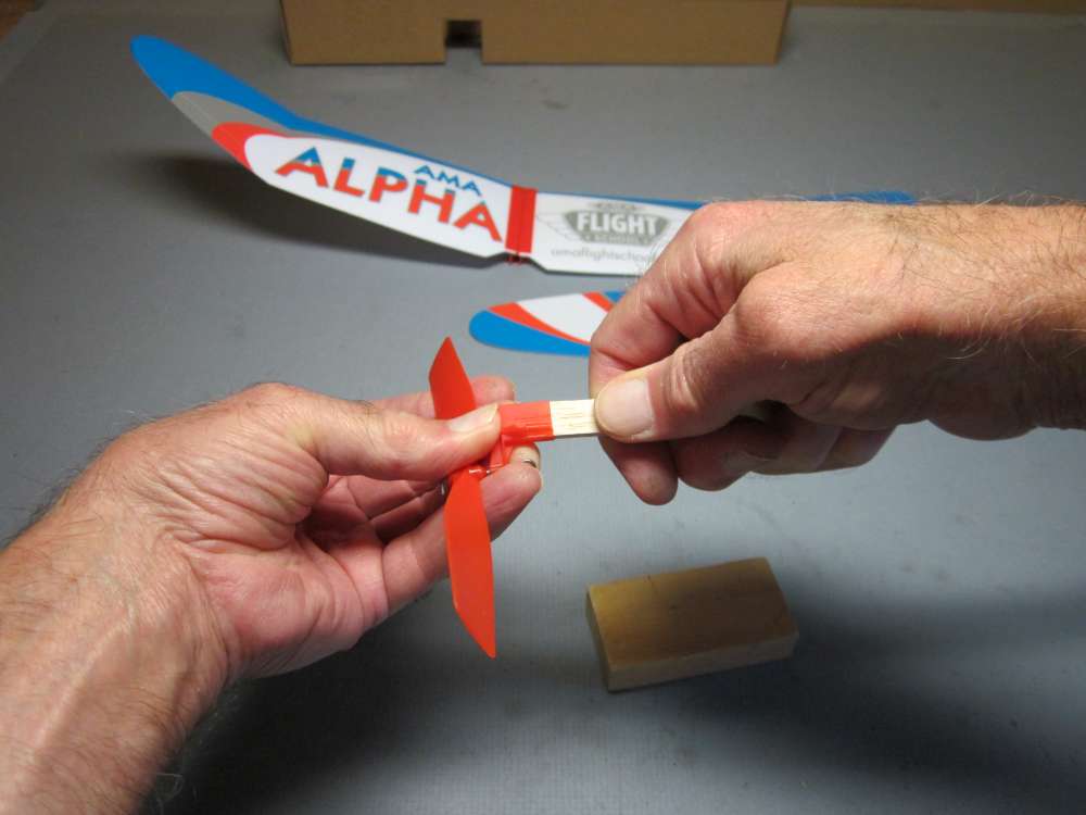
Press the stick into the propeller holder. I couldn’t get this one to go all the way in. This is a pretty hard stick, 14# density. It isn’t necessary to get it in all the way, as long as it is aligned straight and is firmly attached. You do’t want it to shift.
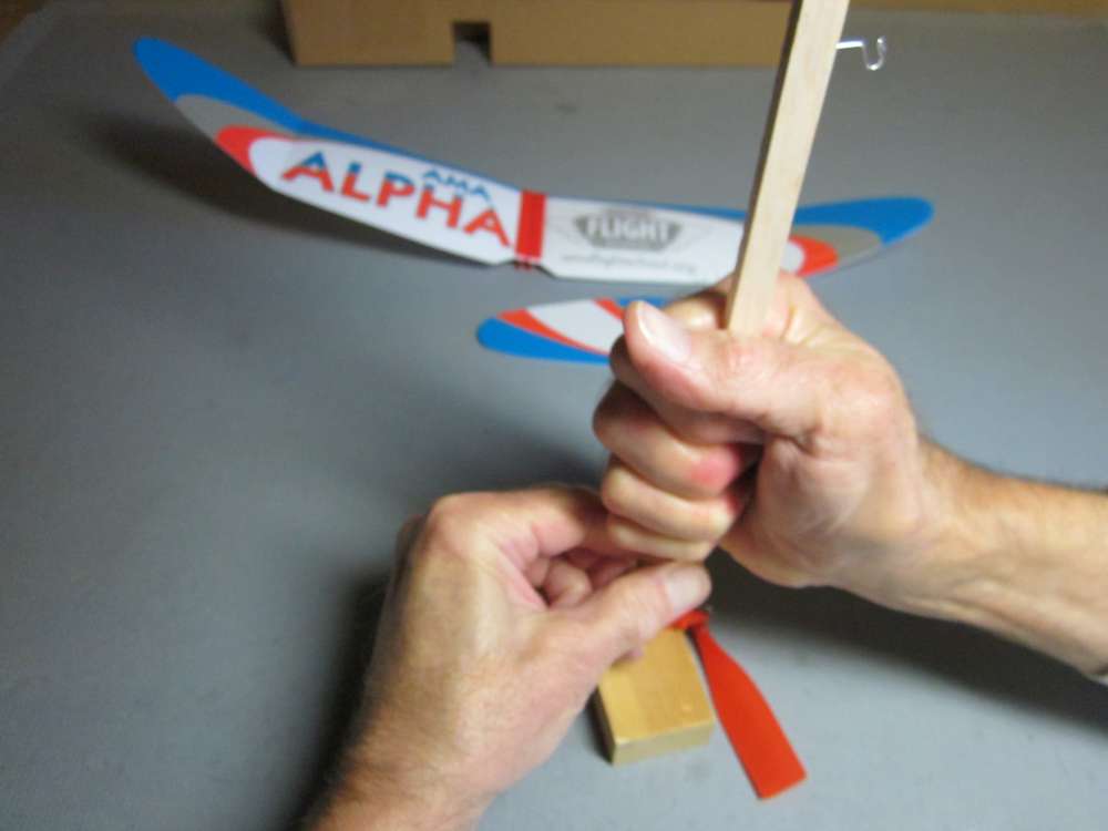
You can put the propeller holder against a hard surface with the propeller extending over the edge and press the stick in further. Hold the stick very close to the holder when you do this. Holding it farther away may cause it to bend and break.
Inserting the tailplane and fin is easy enough, but the thin foam can buckle if not done with care.
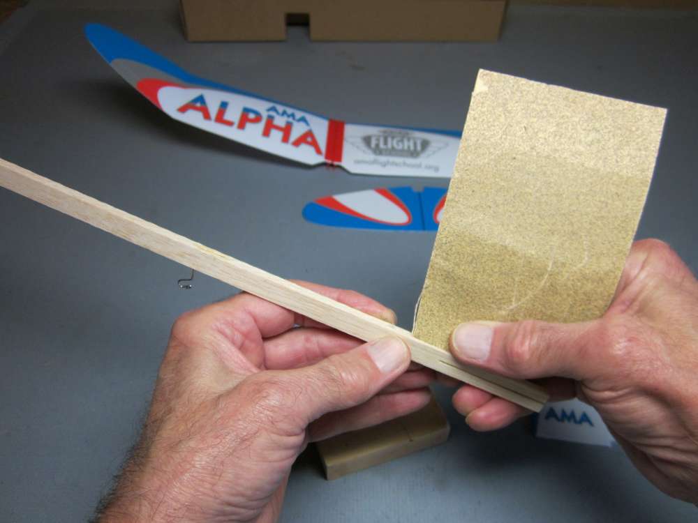
The fin goes into the slot on the top of the stick at the back end. This slot may have some balsa fuzz left in it from the saw. This fuzz can interfere with getting the fin into the slot. Fold a piece of sandpaper in half so there is sand on both sides of the fold and insert the fold into the slot. Slide it back and forth a few times gently to remove any remaining fuzz, but avoid widening the slot.
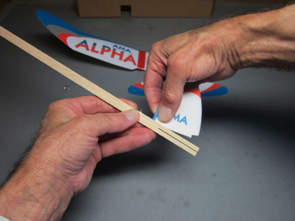
Hold the fin near its leading edge and close to the bottom. Slide the front corner into the slot.
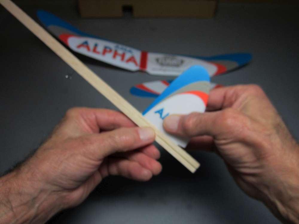
As you slide it forward, rotate it down into the slot. Finally, still holding it close to the bottom, press it firmly into place. This thin, soft foam bends easily. If you push from a distance from the inserted edge, it may buckle.
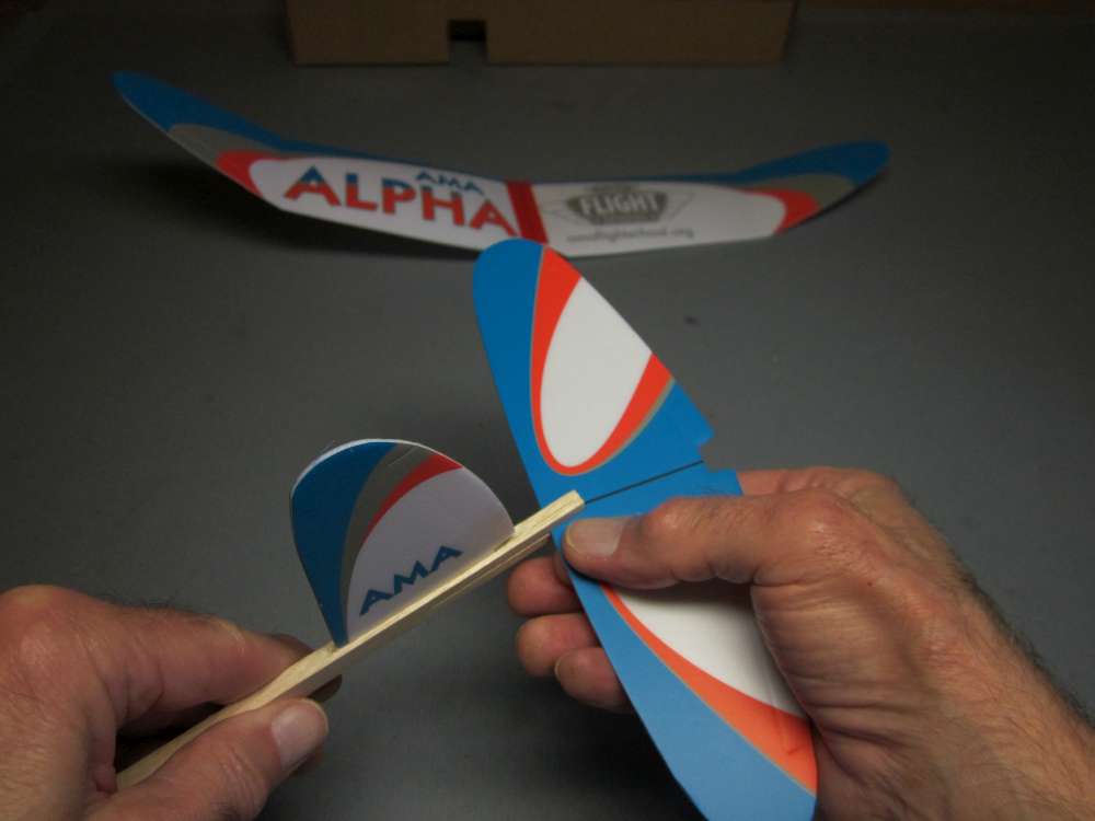
Hold the tailplane close to its leading edge near the center and get it into the slot in the stick.

Pull, don’t push, it into place. You can put the opposite end of the stick against your belly and pull the tailplane in with both hands.
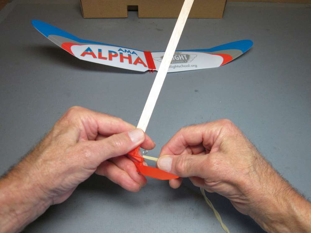
Initial power flights will be made with the recommended 12″ loop of 3/32″ rubber strip. Loop the propeller end of the motor, opposite the knot, onto the propeller hook.
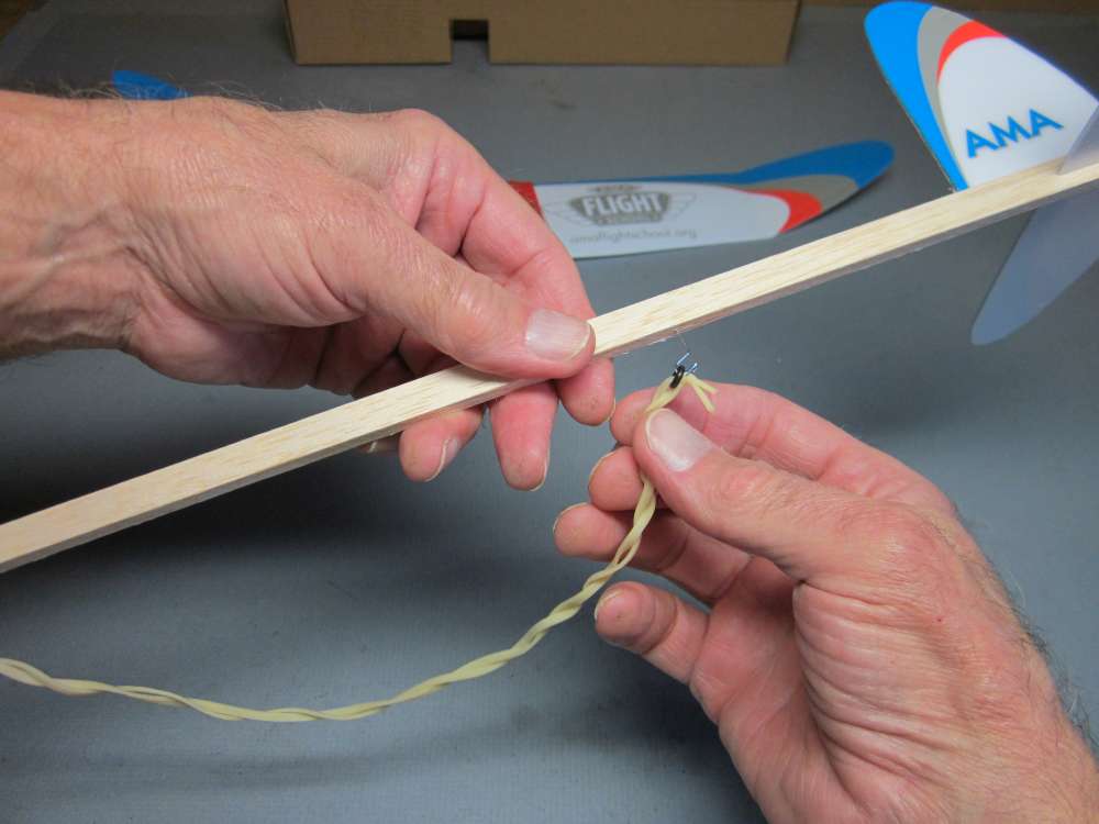
Hook the back end of the motor onto the rear motor hook. Here I have used a 1/8″ O-ring to make it easier to get the tightly wound motor off the winder and onto the hook.
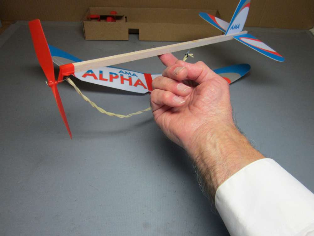
The instructions say to place the wing 4″ behind the propeller holder. That location will vary with the density of the wood. This is an unusually heavy stick, so I am going to try something a little different. I slid the stick back and forth on my finger until it balanced.
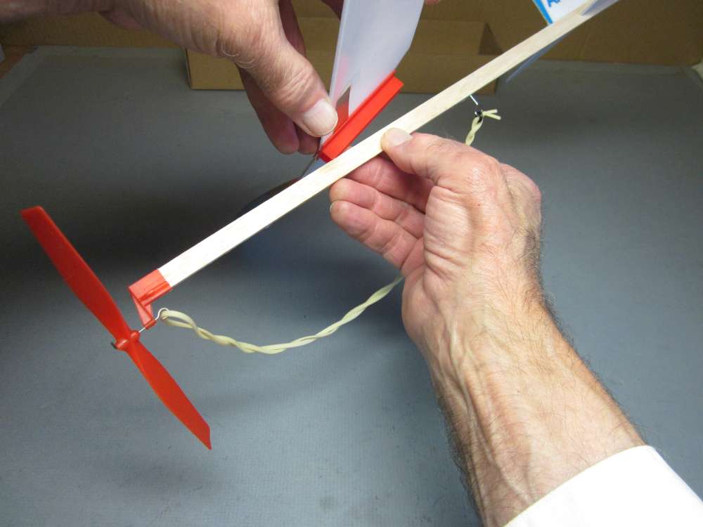
Start one corner of the wing clip onto the stick, positioned so that the middle of the wing clip corresponds to the balance point of the fuselage.
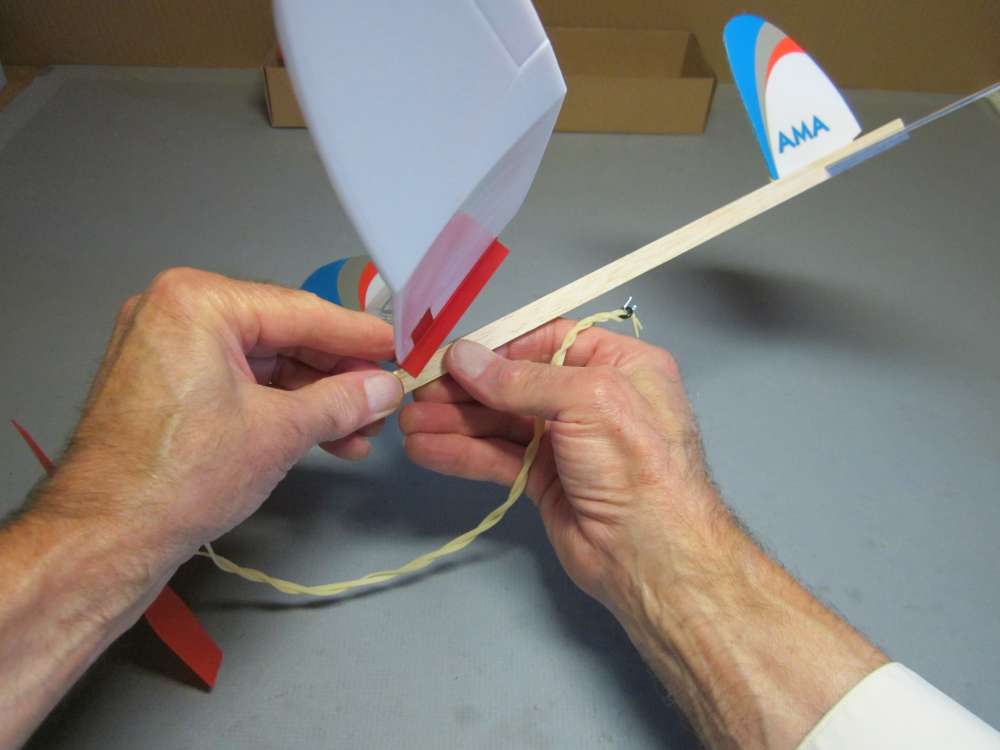
Press it all the way on.
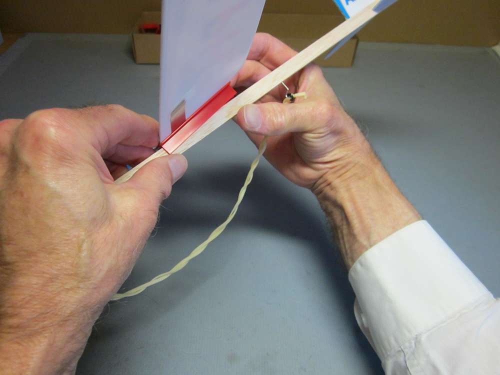
Then, while holding the front edge in place, rotate it onto the stick.
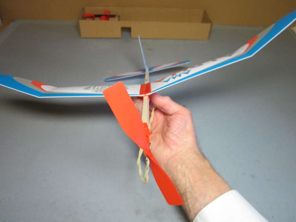
Press it down so there is no gap between the clip and the stick, fore or aft.
This put the wing 4 3/4″ behind the propeller holder. Even here the plane stalled badly with 600 turns on the motor. I had done some glide tests that suggested the wing should be set so the center of gravity of the fuselage assembly should be 1 3/32″ behind the leading edge of the wing. (Later tests suggested slightly different positions. Final position will be determined by test flights. Powered flight tests found that the plane with motor on should balance 1 1/4″ behind the leading edge.) We need a more precise location for the fuselage center of gravity.
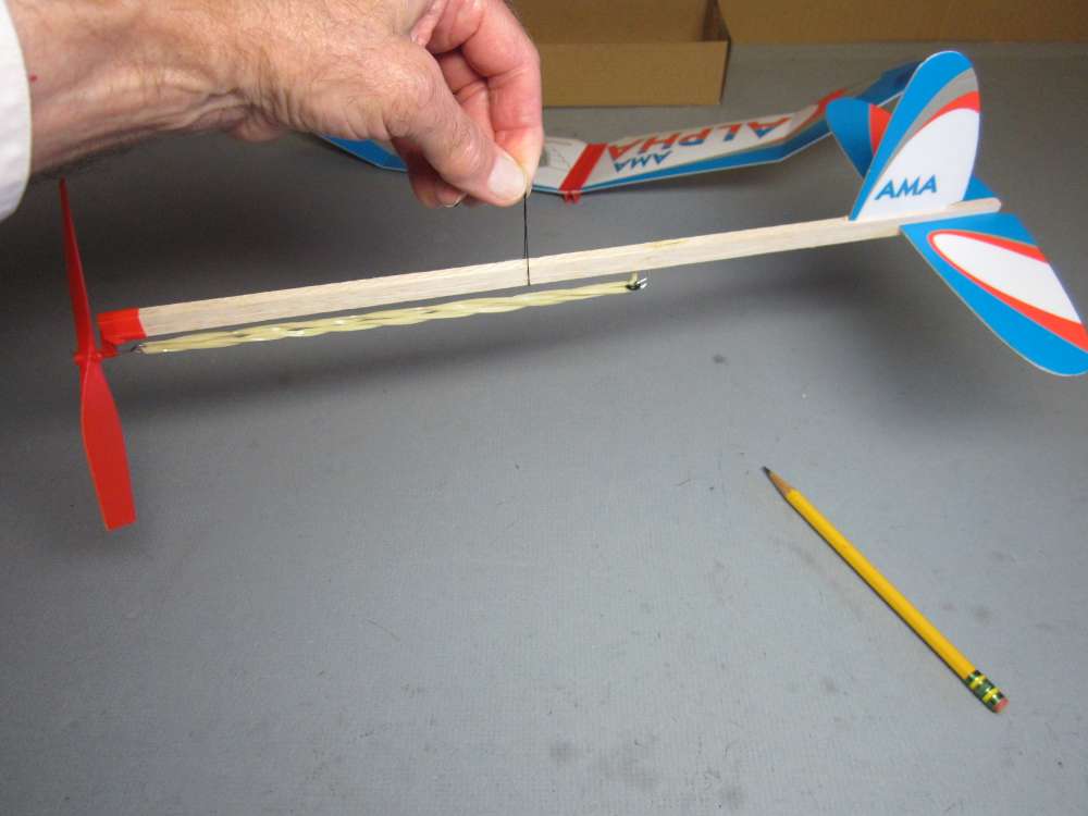
To do this, we double the motor between the hooks to keep it straight and suspend the fuselage assembly from a loop of thread. Move it back and forth until it hangs horizontally. It is a delicate balance.
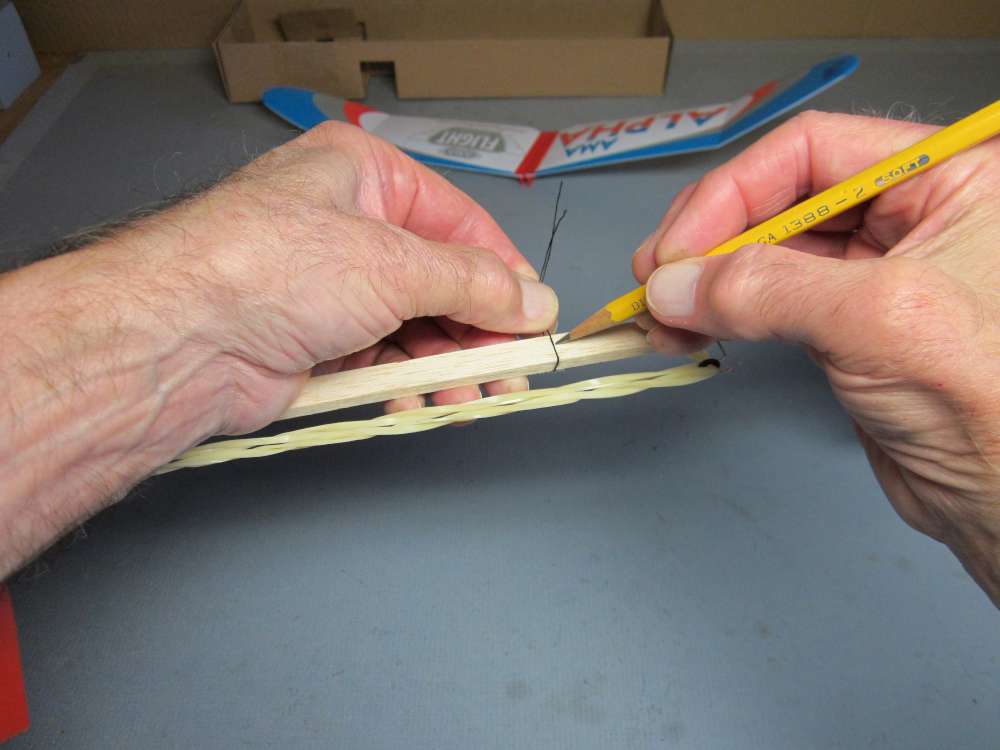
Hold the thread in place and mark the position of the thread on the stick.
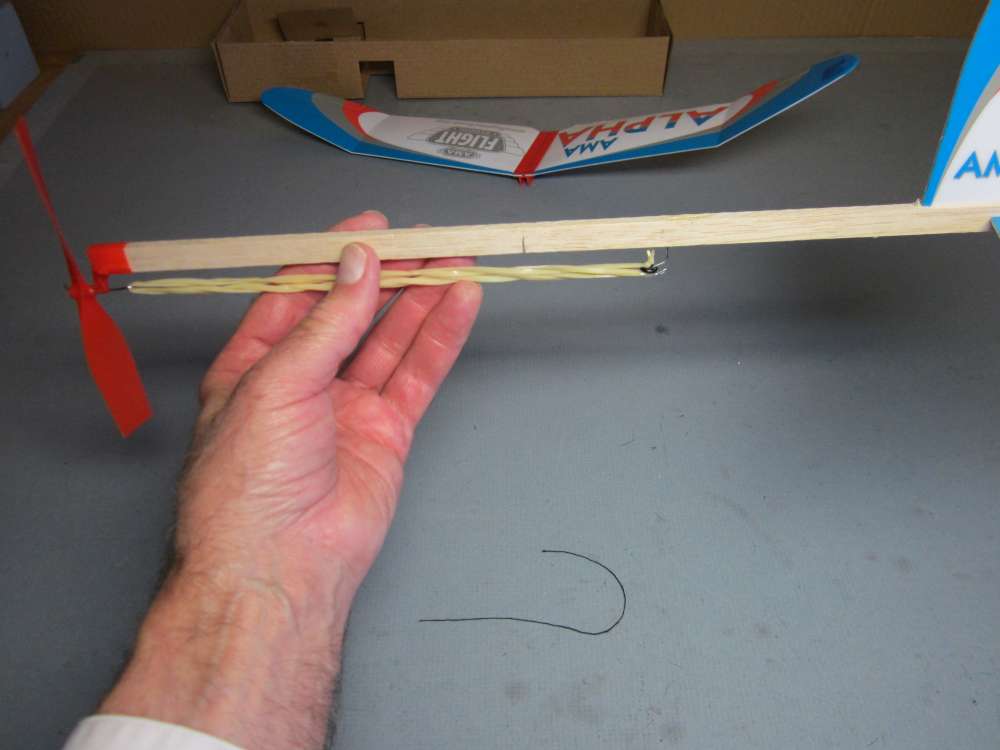
Darken the mark to make it easily visible.
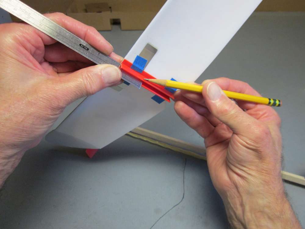
Put a pencil mark on the side of the wing clip 1 3/32″ from the leading edge. (Later I found that 1 1/16″ works better. Your plane may differ.)
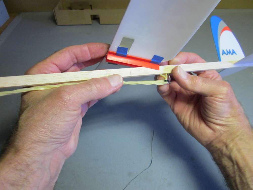
Put the wing back on.
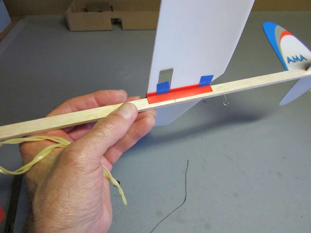
Adjust the wing position so the pencil marks align.
Even this produced a stalling flight. I moved the wing back until it made a straight, smooth climb with 600 turns. That put the wing leading edge 5 5/16″ behind the propeller holder. The fuselage center of gravity mark was 5/8″ behind the wing leading edge. I recommend you start with your center of gravity 5/8″ behind the wing leading edge. A lighter stick will allow you to put your wing closer to the front. This stick weighed 4.6 grams. (Powered flight tests with a 12″ loop of 3/32″ rubber favored putting the fuselage CG 1 1/16″ behind the wing leading edge. Different weights of stick and motor could favor a slightly different location.)
glide testing
Glide Testing is done as a way to establish the CG position for minimum sink.
powered flight tests
Powered flight tests are done to verify the CG position, set turn radius in powered climb and descent, collect data for optimizing motor dimensions and test propellers.
Sizing the motor
Motor sizing is an art. It is partly about how you chose to fly your plane. There are engineering principles to size the motor according to your performance goal.
modifications
Some modifications to consider: move motor hook farther back, use longer motor, sand off excess balsa, use a 7″ prop, make a wing saddle with cambered center section, add landing gear.
Chuck Markos has these suggestions.
“The photos attached show a modification that I made. Basically just shortening the wing clip so that it stops at the metallic reinforcement. No bending of said metal is required to provide dihedral although a bit more probably won’t hurt. An advantage is that the wing airfoil is not disturbed. Regular masking tape was OK as long as it is removed after each flying session. Note that attachment of wing and clip is elevated at one end. Some extra nose weight was also required.
The Alpha flew much better with these changes.
Other Ways to Fly It
Catapult glider, tow glider, high-start glider, kite, ROG. See the AMA Alpha Master Class for examples.
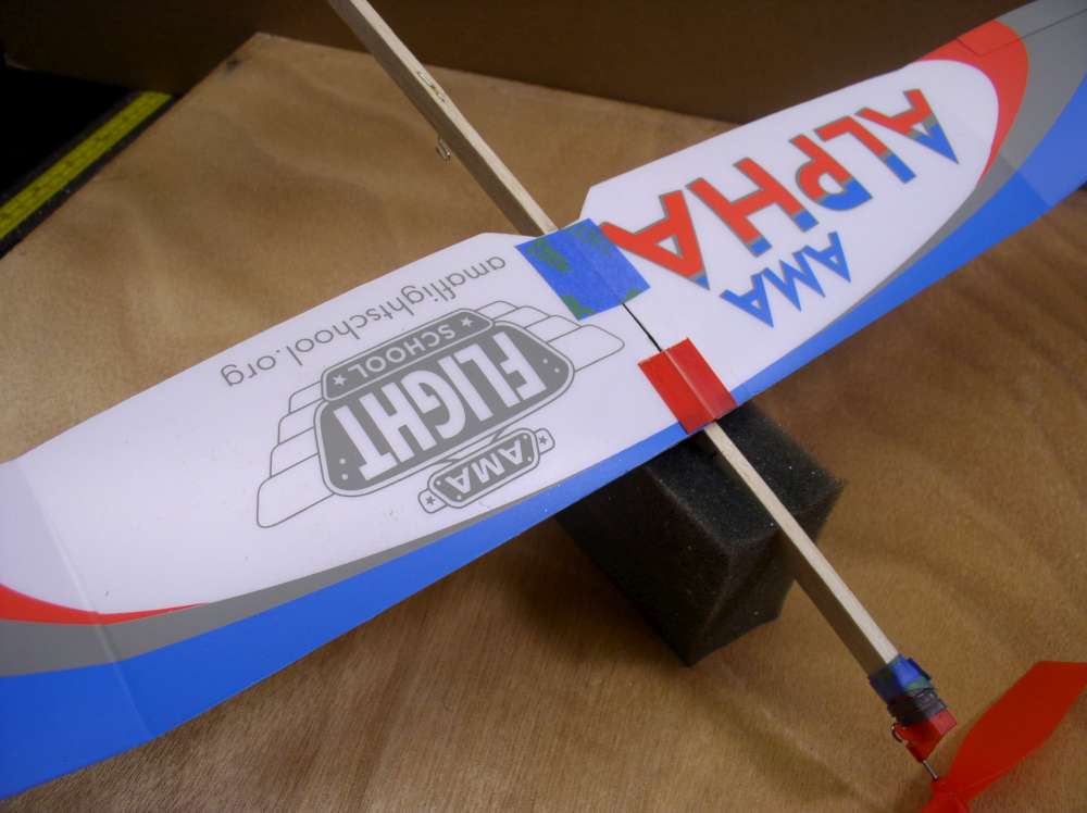
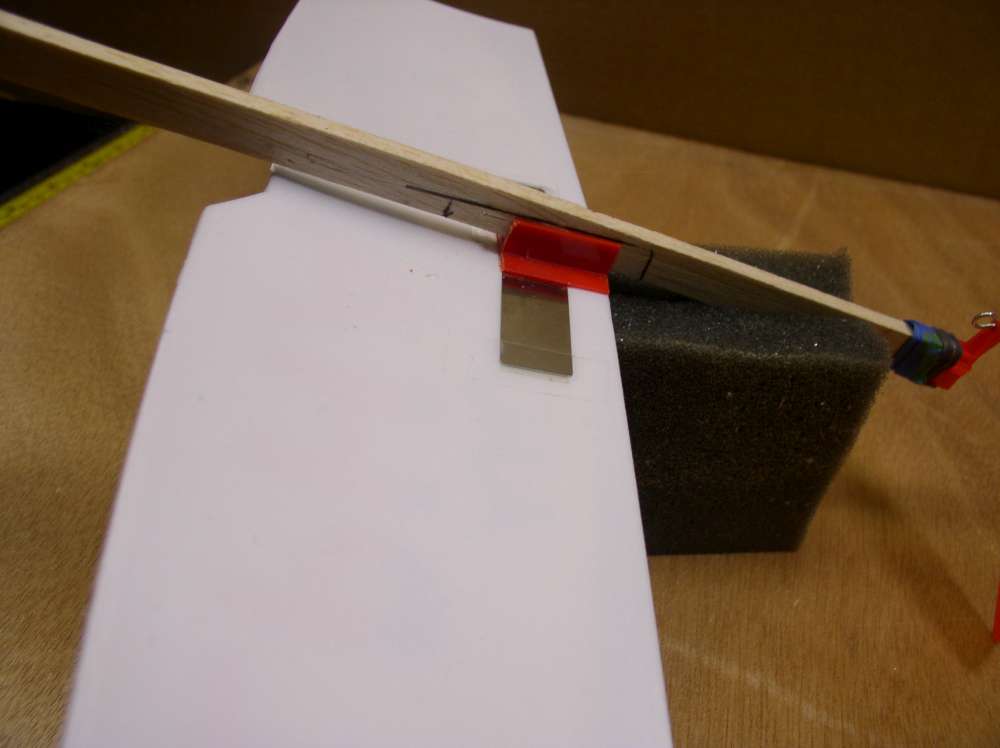
Hi I live in England and ordered two Alphas from the AMA in November 2020. The plan was to give them to two of our grandsons as Christmas presents. But with Covid restrictions and a lockdown preventing me from getting out to test and trim the models at my club flying field I decided to wait before I could check them out before giving them to grandsons. Yesterday was the first day of calm conditions since virus restrictions were eased, so I went to my club field in Essex and flew one of the Alphas. It flew well and after increasing to about 1400 turns it climbed steadily and with assistance from a thermal was carried across the club field and landed in a 10ft tall hedge. It was immediately clear that the model ideally needed the polyhedral wing for stable flight, as listed on the outside of the box. But I could find nothing in the instructions to show how to add a second bend to the wings. I then looked at some of the AMA videos about the Alpha and noticed some flown in the postal contest were flying well and looked so much better with the polyhedral wings. I was about to write to the AMA for guidance but did a quick Google search for any info and that’s when I found your brilliant website. The section on assembling the wings solves the problem and no doubt I will have both models suitably trimmed for the next time we have calm conditions here in Essex. Thanks very much for the great website. Regards Bill Stock, Chipping Ongar, Essex UK
PS I am a member of a small model flying group which specialises in mainly vintage gliders and power models, (using only electric motors) both radio-controlled and some free-flight.
Great and unbelievably detailed overview! Thanks! It doesn’t seem to mention the model has all flight controls needed for trim….you don’t need to add clay at a wingtip. Bending the aluminum clip for a bit more dihedral is a good mod. The prop front bearing has also been lowered so rubber does not bind up with knotting like the older bearings. The propeller is also much more refined and molded. Just a note from the fellow who designed and manufactured the model. To respond to John, you should be thankful a die hard long term modeler has the contacts in China to get this done with winder for that price. Also FAI rubber is imported to China from the USA for inclusion in the kits. I personally oversee production in Shenzhen and be sure quality is assured and consistent. The BETA is coming shortly and is even better. I love to see folks modding ALPHAS. Hook some heavy rubber on it and fly it outdoors. So far longest flight in Denver is over 9 minutes…….8 of which is thermal flying with free wheeling prop. I welcome comments rob@eclipsetoys.com
Found this page while researching prop size vs wing loading. I’m putting together plans to have an indoor fun fly for the local youth this winter so finding your site is extremely timely and a wealth of info, thanks! I suspect we’ll enter one of your postal competitions as well.
Individual AMA Cub kits manufactured by Sig retail at $7.87 each, although Sig sells them at $5.25 plus post from their online store. The bulk pack of 35 is sold by the AMA for $53.99 or $1.55 each. The AMA Alpha is also sold in bulk, although that is not listed in their online store. The bulk pack can be purchased through the AMA Education department. The bulk pack comes with 50 Alphas. Winders are not included with this option, and the cost is $297.50 or $5.95 each. I suspect that AMA would talk about other combinations if teachers contact them. Flying in a school gym would not require more than a couple winders, so a teacher could order a bulk pack and a couple individual planes with winders.
It is not just about cost. The AMA Cub requires a teacher and several assistants, depending on class size, who are familiar with teaching the AMA Cub. It requires razor blades and glues which are discouraged in schools. It takes 30 to 45 minutes to build and a while to trim. Classroom teachers generally just don’t have the time. The AMA Alpha takes about a minute to put together. Making the motor takes a little longer than that. I and the AMA staff are developing classroom curricula to support teachers in using the AMA Alpha in science, engineering and math instruction.
If the AMA Alpha was manufactured in the USA the cost would be much more out of line for a school project.
It is too bad that the AMA, our national organization, felt the need to go to China for the manufacture of the Alpha. $7.95 plus $5.00 for shipping. Way out of line for a school project. The Delta Dart at $1.40 per kit is a much better deal and it also teaches construction.