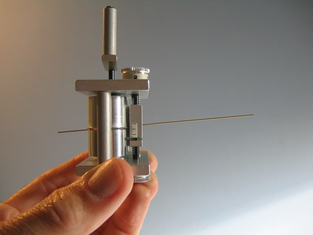
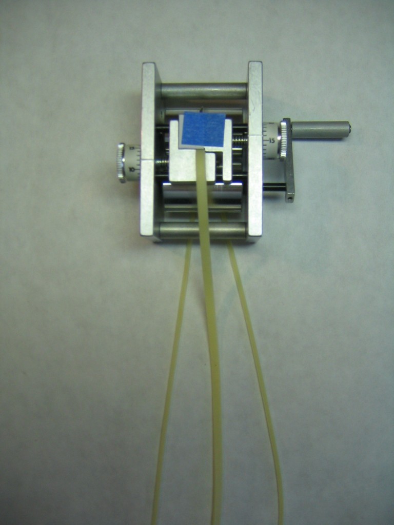
Those of us who understand the relationship between airplane, propeller, rubber motor cross section and flight performance want to control the motor cross section by stripping the rubber to the required width. Ray Harlan sells a tool that cuts standard widths of rubber into whatever width you wish.
http://www.indoorspecialties.com/index1.html
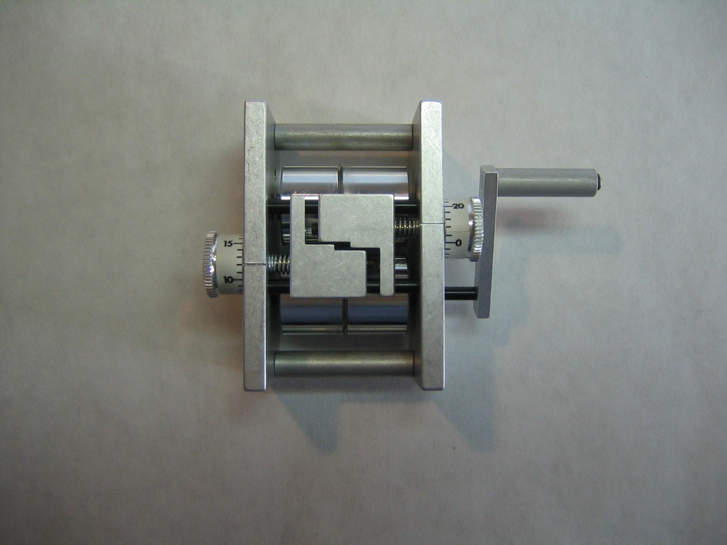
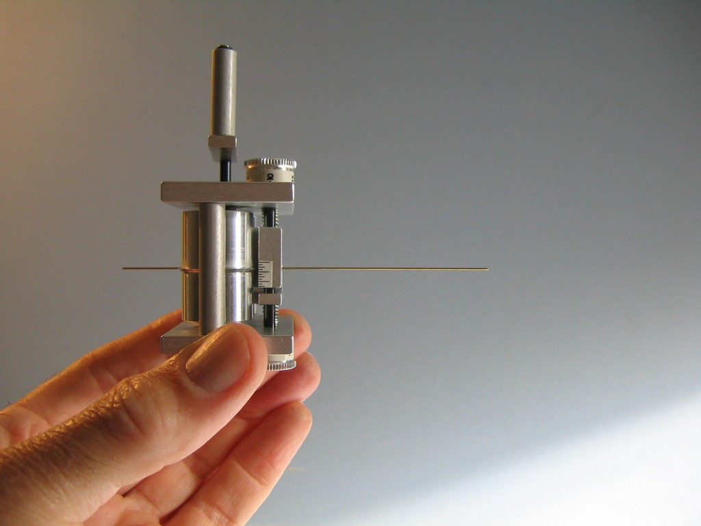
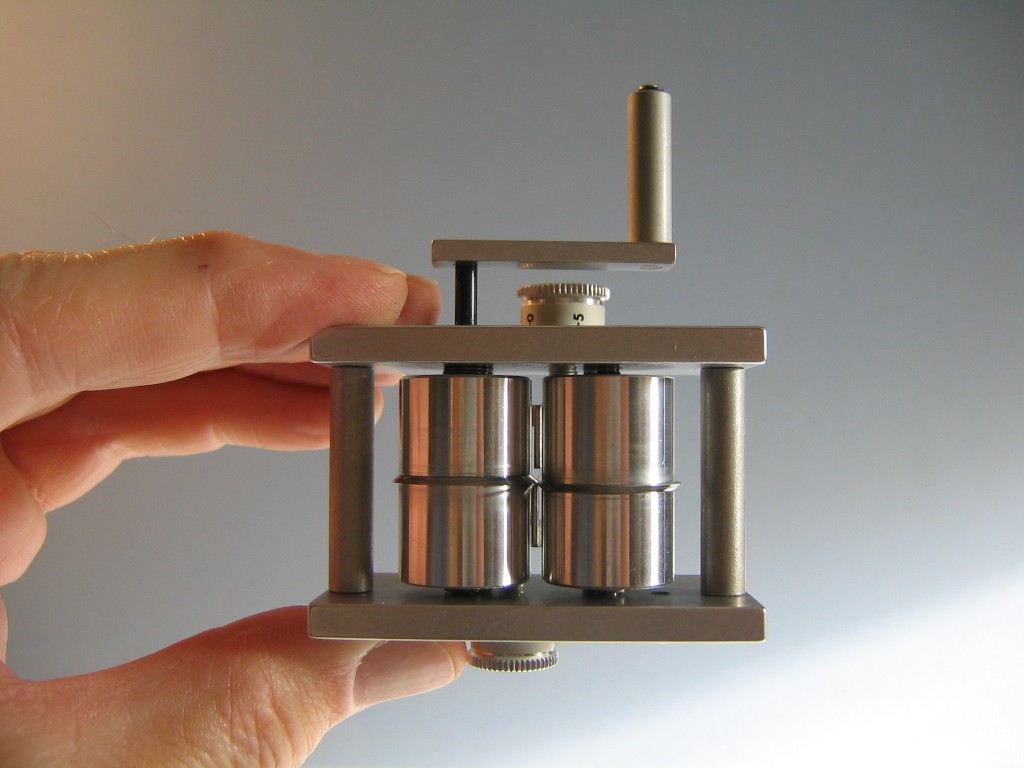
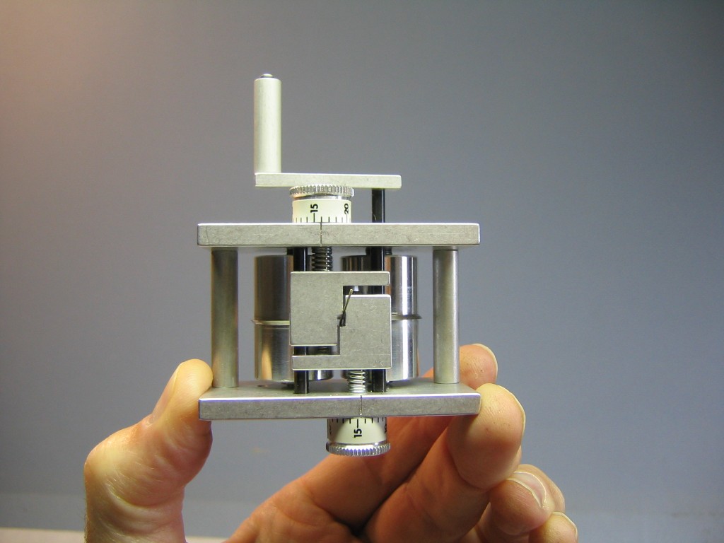
Two fences in front form a slot that guides the rubber strip into two overlapping, rotating disk knives in the back. The positions of the fences are set by screws driven by numbered dials on the sides. The rotating disk knives are turned by a crank on the right side. To strip a standard width into a smaller width, the fences are set apart a distance equal to the width of the standard strip and the two fences are positioned so one edge of the strip is the required distance from the cutting plane. Setting the fences in the correct position requires calibrating the dials to place the fences the correct distance from the cutting plane and each other. Each division on the dial represents a one thousandth of an inch (1/1,000″ = 0.001″) movement in the position of the fence. There are 25 units around the circumference of the dial, corresponding to 0.025″ of movement in the fence. Each rotation of the dial moves the fence 0.025″ and brings it back to the same number on the dial. This means that the dial number of a fence position is a modulo 25 number; it is expressed as some integer times 25 thousandths plus a remainder, the integer being the number of complete rotations of the dial. For example, 0.065″ = 2 x 0.025″ + 0.015″. In dial units, we could express this as 65 = 2 x 25 + 15 thousandths.
Calibration requires knowing the dial setting that exactly aligns each fence with the cutting plane. You can then open up the gap on each side by the number of dial units necessary to get the widths you want. Initially I tried to line the fences up with the edges of the cutting disks by eye. This produced unreliable results, as it is difficult to judge exact alignment. Each time I tried it I got different numbers. I tried plotting the results of stripping rubber, by weighing the original strip and the resulting cuts, but that also proved unreliable. It is difficult to judge the snugness of the fit of the strip in the slot. A little difference on either side will affect the result.
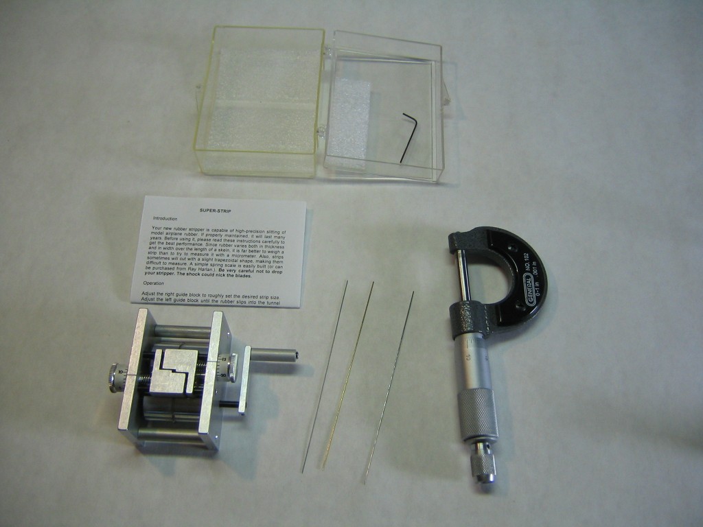
I devised a method of catching a piece of wire of known diameter between the fence and the cutting blade, reading the dial setting and subtracting the wire diameter from the setting to get the dial reading corresponding to the cutting plane. The wire can be about 4″ long and it must be perfectly straight. File the sharp cut ends round so you won’t poke yourself. Check it against a straightedge, rotate it 90 degrees and check it again. Roll it on a very flat surface. If it rattles, it is not flat. If it rolls smoothly with very slight inclination, it is flat. It must be straight to within less than 0.001″. Measure the diameter with a micrometer. Make two measurements at right angles to each other. They should be exactly the same. I found that 1/32″ = 0.03125″ wire was too thick to seat properly on the blade without impinging on the conical surface of the opposite blade. I found that 0.025″ wire worked for one side, but may have been too big for the other side. I thought I could see a small gap of light between the wire and the blade. I did calibrations with 0.020″ and 0.015″ wire.
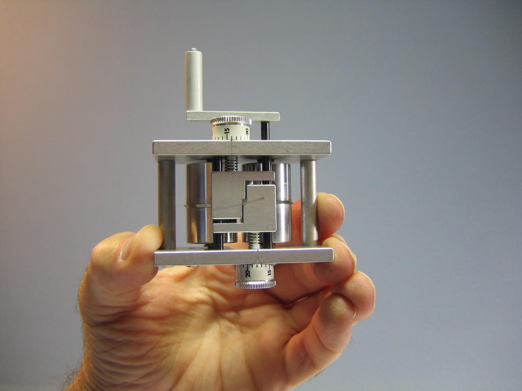
Start by setting one fence about one wire diameter below the cutting plane and back the other off to give plenty of clearance, about 0.1″. Insert the wire into the stripper so it rests above the fence, below the blade and more sticks out in front than in back.
Check in back that the wire is on top of the fence and under the cutting blade. This arrangement keeps the wire from falling down in front and its weight holds it against both surfaces as the dial is turned.
Now turn the dial that controls the fence the wire is sitting on to move it up until the blade pushes the wire down in back, causing it to rise in front. This means the gap is narrower than the wire diameter. Turn the dial the other direction until the wire just lies flat on the fence.
It is easier to judge exactly where the wire is in relation to the fence when looking directly from in front, in good light. Now aren’t you glad you filed the sharp point off that wire?
Turn the dial and watch to see when the gap between the wire and the front edge of the fence just disappears. Record the dial setting. With a wire diameter of 0.020″ and a dial setting of 18, corresponding to 0.018″, this means the cutting plane is 20 thousandths lower than 18 thousandths, at 0.018″ – 0.020″ = -0.002″, corresponding to a dial reading of 25 – 2 = 23. Make ten readings of each fence with each size of wire. Average the dial readings of the cutting plane for each fence. There was considerable variation in the readings, so I also calculated the standard deviation.
I found that the cutting plane position of the left fence had a dial reading of 22 with a standard deviation of 0.46 and the right dial reading was 24 with a standard deviation of 0.10.
These numbers allow us to set the dials to cut whatever width we want. As an example, let us cut a nominal 1/8″ strip that measures 0.130″ on the micrometer into two equal halves of 0.065″. We want to move the fences 65 thousandths from the cutting plane on each side. The cutting plane is 3 units below zero on the left dial, so we must move the dial 65 – 3 = 62 units above the zero. In modulo 25 arithmetic, 62 = 2 x 25 + 12. So we start the dial at 22, move it up 3 units to 25 = 0, turn it two full rotations to 0 again, then rotate it 12 more units. The cutting plane is 1 unit below zero on the right dial, so we must move the dial 65 – 1 = 64 units above the zero. In modulo 25 arithmetic, 64 = 2 x 25 + 14. So we start the dial at 24, move it up 1 unit to 25 = 0, turn it two full rotations to 0 again, then rotate it 14 more units.
This establishes formulae for setting the dials to cut a width w from a strip of width W, measured in inches. The general formulae for the dial settings are, for the left dial, set the reading to 1,000 x w – 3 modulo 25 and set the right dial to 1,000 x (W-w) – 1 modulo 25.
Always measure the width of the strip you are cutting with a micrometer. It may be a good idea to measure at both ends to verify consistency.
I cut four pieces of rubber with the same settings. There was some variation in widths, determined by weighing the original strip and the two resulting pieces. The variation appeared to be random, with sometimes the left piece bigger and sometimes the right piece bigger. The standard deviation in all 8 samples was about 0.001″, or 1.5%. The left pieces averaged 0.06526″ and the right pieces averaged 0.06474″, only 0.8% different. Considering that my weighing process is good to only about 1-2%, that’s as good as I can call it.
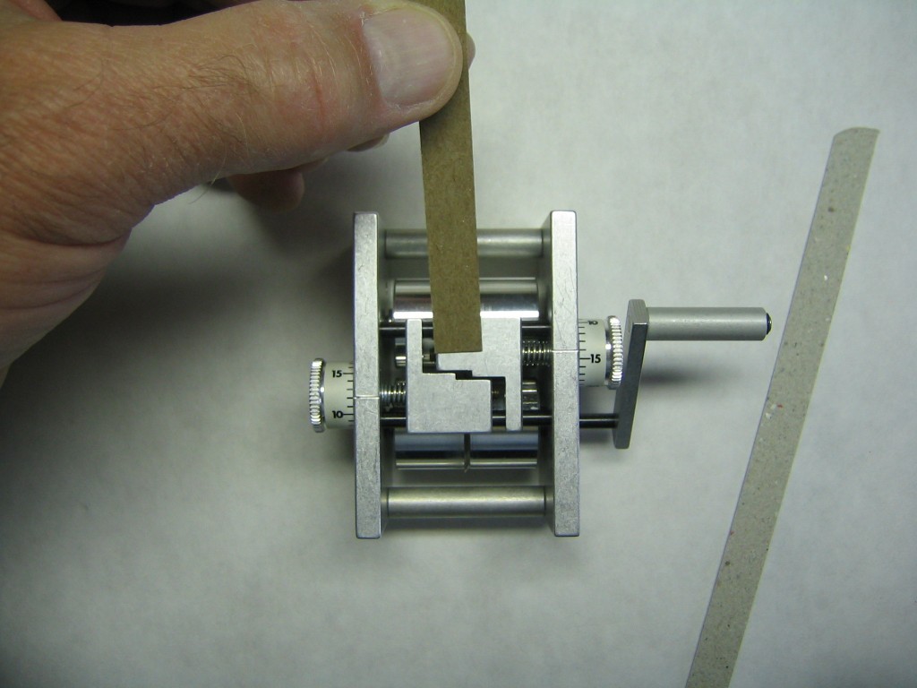
One possible source of the variation in cut width is that the strip can rotate slightly between the fences. If the strip goes through the blades canted, the cut will not be square and the pieces will have trapezoidal cross sections. I cut a strip of thin cardboard to use as a “tongue depressor”, to keep the strip flat in the gap.
Set the dials and cut a strip of thin card to fit.
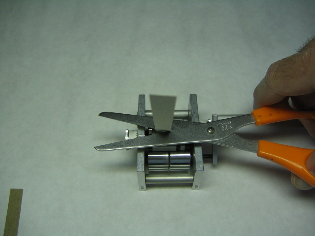
Insert the strip into the slot until it touches the blades, then cut it off about 3/8″ above the face. Withdraw it a tiny bit and crease it slightly against the block. Pull it out and fold it cleanly at the crease, so the edges line up.
Open each dial a notch to make it easy to get the rubber in and push it in until it engages the blades.
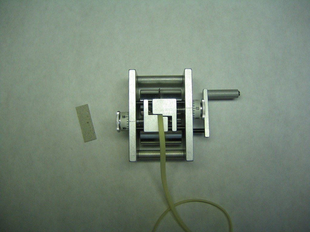
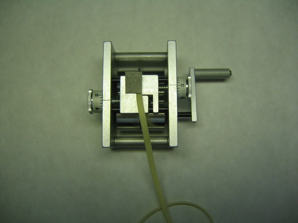
Slide the cardboard into the slot.
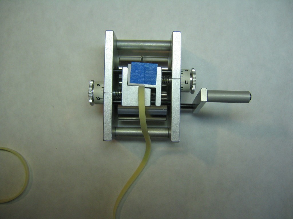
I held the card in place with my thumb the first time, but taping it down works, too. Don’t forget to reset the dials to the proper settings if you opened the gap to make it easier to get the rubber strip into the slot.
Proceed to turn the crank and strip the rubber.
This seemed to make a more uniform cut. With more cuts, I will get enough measures for statistical evaluation.
I found that coating the strip with cornstarch reduced the friction between the rubber and the guide blocks. I put the strip in a baggie with cornstarch and shook it up. I took it out and snapped it a couple times to knock off most of the cornstarch, leaving only a thin coating. This allows much more consistent cuts. Cornstarch will accumulate on the stripper. Blow it off or remove it with a fine brush. Clean your stripper before putting it away after each cutting session.
Following up on Ray’s comment, below, I make a first cut based on a calibration formula, as described above. I weight the resulting strips and adjust the dials accordingly. Write down the dial settings and weights so you can reproduce the result. I found, as Ray says, the rubber itself is not uniform, so there is no way you can make precise cuts. If you stretch a piece of rubber strip, the thin places will neck down more than the thick places and the differences become more visible. You will see that rubber strip is quite lumpy.
–
Halfway through stripping some rubber the handle bound on the dial and the drums on the handle were loose. Now I can’t get it to cut at all. How do the blades have to line up ? However I seem to tighten the drum halves the handle binds on the dial .
I am not entirely clear what you mean. It sounds like the set screw on the handle might be loose, allowing the handle to move inward and strike on the dial. Check whether you can pull the handle out on its shaft. If it is loose, place it so its outside face corresponds to the end of the shaft and tighten the set screw. The Harlan Stripper comes with an 0.035″ Allen wrench for this purpose.
Dear sir.
Rubber Stripper is made from black
nylon,shafts-stainless steel and rotary blade is from HSS steel. Dimensions
without holder is 47mm x 49mm x 66m.
Can stripp 1/4 ” (6,4mm) down to 0,030″ (0,77mm) This stripper is suitable
for all user – F1D , Pistachio scale,Peanut scale and WakeField model.
Video http://www.youtube.com/watch?v=jABBqJaIZF4
If you have any more question,you dont hesistate and contact me!
Best regards
Jaromir Hendrich
Gary has put a lot of effort into working out a calibration technique for my rubber stripper. However, he assumes everything is linear, when it is not. The width of a cut depends on how much friction the guides have on the rubber and what the ratio of the cut width is to the remnant strip. I have never been able to define a formula for cut widths.
However, all is not lost. The width of a strip is not the important parameter. It is the weight of a strip, or, more importantly, the weight per inch of that strip. As I point out in my instructions, weighing uncut strips and setting them in increasing order of increasing weight (cut strips somewhat longer than twice the motor length) will let you get the most consistent motors. You also will notice that raw strips can have weight differences up to about 10%, which says the strip isn’t constant in thickness, which is the whole reason for measuring weight and not width. You do need to start with a width measurement, so cut a piece about an inch long and measure it. Adjust the guides until the strip is about what you think it should be, testing more one-inch pieces. Then cut the lightest raw strip and weigh the cut piece. Adjust the guides to get a better weight. There should be just a little friction on the rubber. Tighten the left guide until you can’t push the rubber in and then back off .0005 to .001. Cut the second piece and weigh it. Continue adjusting and cutting until you get just what you want. As the pieces get heavier, adjustment must be made to compensate, making the strips narrower.
If the raw strip can yield several motors, start from the heaviest piece and go backwards after going through all of the strips once. There is a learning curve again because the remnant strip is much smaller, but it should be a quicker adjustment to the correct size.
Lately I have been marking the weight per inch on my rubber envelopes. That lets me organize motors in a more useful order. It also lets me know if I use about the same weights per inch for different models so I can steal a motor from another bag if necessary.
This method can let you get a lot of motors within a percent of your target. It is the only way to consistently cut rubber. And that trapezoid cut that Gary mentions? He has a good solution for minimizing it, but I don’t think it is very important either. It’s the motor weight that counts.
There are only two rules for taking care of your stripper:
1. Don’t drop it, which will nick the blades.
2. Don’t lend it. The lendee will drop it!
Ray, your rubber cutter is the coolest thing I ever bought for my hobbies. You are a hell of a machinist….either that, or you know one! Anyway, thank you for a great product.