building and flying an indoor big pussycat
By Gary Hinze
Copyright notice: You may print one copy of this tutorial for your personal use only.
This tutorial contains detailed, illustrated instructions for building and flying an indoor Big Pussycat model airplane.
introduction to the big pussycat
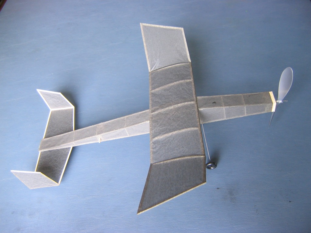
This is a Big Pussycat. It is a rubber powered free flight model airplane. It was designed by Dick Baxter and published in the December 2006 Flying Models magazine. It is a 16″ version of his 12″ Pussycat. It also differs from the Pussycat in having cambered wing ribs and in being a little lighter for its size. It flies better. It was designed to be an easy model for beginners to build and still be a great flyer.
I have added removable landing gear so it can be flown ROG (Rise Off Ground) if you like.
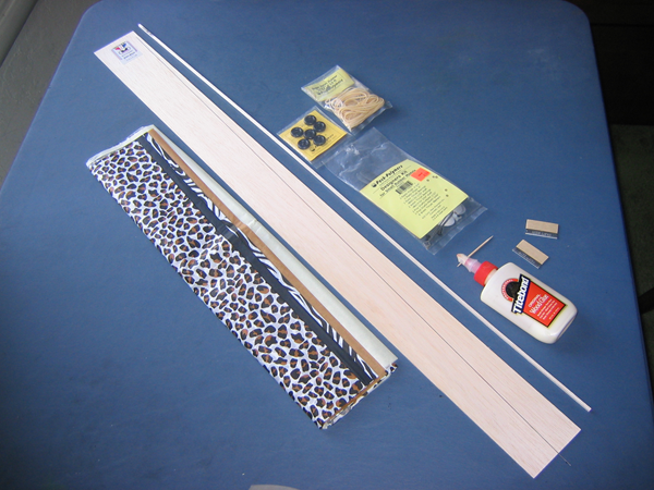
There is no kit for this plane. The builder must buy all the materials and make everything from scratch. One thing you learn from building model airplanes is that wonderful things can result from taking one small step after another, adding one small part at a time. This airplane started as some pieces of wood, tissue paper, wire and plastic, with a little glue to hold it all together. There is enough material here to make two Big Pussycats, with some left over:
Part of the reason for this Big Pussycat project was that our class students would build it mostly at home on their own, with minimal supervision. We hoped our students would develop enough confidence to continue building and flying model airplanes on their own, and not depend on us to teach everything in a class. This tutorial was originally sent out as a series of emails to students. It is posted here so you can build one at home.
Plans
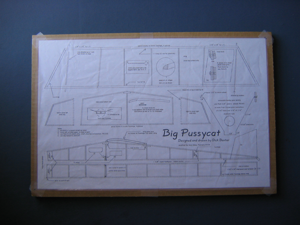
A plan may be found on the Internet at: Big Pussycat Plan or Flying Models .
You may also copy the plan from the December, 2006 Flying Models magazine. The text says it has a 15 3/4″ span. The plan is 15 11/32″ and I wanted it to be an even 16″, so I enlarged it by a factor of 1.043 onto 11″ x 17″ paper at the copy shop. Flying Models has an Internet site from which you may order a redrawn Big Pussycat plan or a combo with an Akro plan.
The first thing you do when building a model airplane is carefully study the plans. Look at each part to determine what material it is made from, its dimensions, how it will be made and how it connects to the parts around it. Read all the notes. Think about the construction sequence and how the sub assemblies will go together. Make a list of the materials and tools you will need to build the plane.
I have made some changes to fly it according to my preferences inside the Gym. The original design has 6 degrees of washout on both wingtips and 6 degrees of incidence on each fin. It flies in 15 foot circles, steeply banked. Outdoors in thermals this may be a good way to fly. A steep bank implies a sideslip which is a downward motion. The airplane is losing altitude faster than I like for indoor flying. Indoors I prefer to fly in circles as large as the hall allows and with the wings close to level. I changed the angles of the dihedral break lines to produce 2 degrees of washin on the left wingtip and 2 degrees of washout on the right wingtip to counter the left roll due to motor torque. I changed the angles on the tailfins to provide one degree of left turn to open up the turn. I also changed the angle of the noseblock to reduce the downthrust of the propeller. We will be flying under a ceiling where a more gradual climb is preferred, requiring a lower torque motor and less downthrust. I have also lightened the nose block, using a single piece for the outer plate and two layers for the inner plate.
You might like to make these changes on your plan before you start, so I will list them here. They are discussed within the relevant sections of the text. You can see them in the illustrated instructions that follow. Some minor changes in details of construction do not need to be shown on the plan, they will be made clear in the text.
1. Change the dihedral break point locations, measured from the centerline, to 3 3/4″ for the left leading edge, 4″ for the left trailing edge, 4″ for the right leading edge and 3 3/4″ for the right trailing edge. Change the positions of the dihedral jigs to parallel the changed break lines at the same distance as shown on the plan. Put the ribs inside the dihedral cut in the spars. The ribs will be glued into the center panel, not the tips. Make the leading edges of the tips from 1/16″ x 1/8″ balsa, rather than the 1/8″ square called out on the original plan. Keep the 1/8″ square leading edge for the wing center panel.
2. Change the incidence angles of the fins to point 3 degrees to the right on the left fin and 1 degree to the left on the right fin, so they are toed in. Measured from the centerline, put the left trailing edge at 3 7/16″, the left leading edge at 3 9/32″, the right trailing edge at 3 3/8″ and the right leading edge at 3 11/32″. The fins have zero lift at minus 2 degrees of incidence, so this puts both fins at 1 degree of effective attack angle turning left. This will open up the flight circle without requiring a right thrust shim behind the noseblock. I also lightened the fins by building only the top three sides and gluing them to the stabilizer tip rib, which then serves as the bottom spar of the fin.
3. Add two pieces of 1/16″ sheet, 5/16″ tall, on the bottom of the fuselage between the uprights below the wing leading edge, to form a box that will hold landing gear wire with a friction fit. One fits between the uprights, the other goes just far enough ahead of that one to make a snug fit for the 0.025″ diameter landing gear wire. Add a 1/16″ x 1/8″ hard balsa tailskid, about 5/16″ long, to the center of the sternpost, to complete the landing gear.
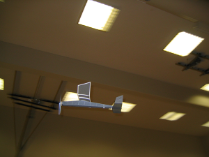
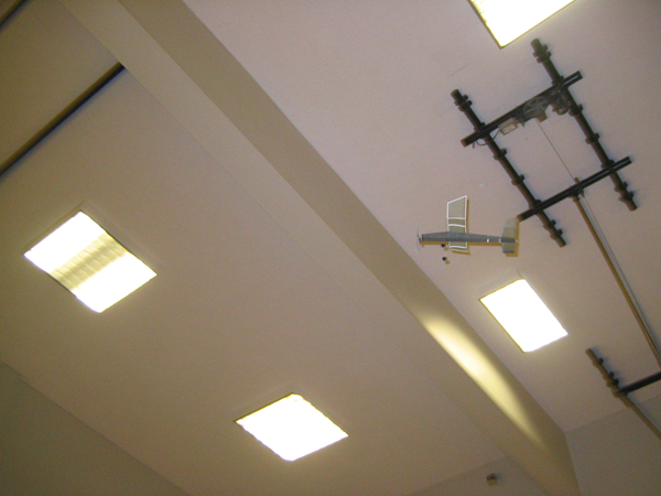
4. Add a crosspiece at the leading edge of the motor peg anchor plate on the bottom of the fuselage to provide a window to let you see the rubber motor and motor peg while getting the rubber loop around the motor peg. You can see this opening in the in flight pictures above.
5. Reduce the downthrust angle at the nose by extending the lower longerons 1/16″ farther forward. Adjust the side nose plates accordingly. This change was made during flight trials by adding a 1/16″ square shim on the bottom of the nose. You might as well build it that way from the start.
6. Add the landing gear wire and wheels. See the section on making the landing gear for details.
To go to Chapter 1, click HERE.
Gary Hinze
Just follow the plan. regards dick baxter dbaxter554@gmail.com
Thanks for this tutorial Gary. I will be taking it up soon, though with the original plan settings.
However I wish to understand a few things:
1. “The original design has 6 degrees of washin on both wingtips..” Isnt it washout and not washin?
2. “Change the incidence angles of the fins to point 3 degrees to the right on the left fin and 1 degree to the left on the right fin… The fins have zero lift at minus 2 degrees of incidence, so this puts both fins at 1 degree of effective attack angle turning left.” How does one know that zero lift is at -2 deg for the fins? And howdoes it come to be +1deg AOA in left circles? I can imagine that during left circles the AOA will be less than the geometric incidence of +3 deg (left fin) and -1deg (right fin), but cant understand after that.
3. As per 1st question (I think it is 6 edg washout), is washout on both wingtips better/ inferior than washin on inward wingtip and washout on outward wingtip? I believe models of both types are designed. What does washout on both wingtips achieve? Is it just that washout on both wingtips will have steeply banked flight (with washout preventing tip stall and still providing lift during circles), while washin on inward wingtip will have a more leveled turn?
You are right, it is washout. Washout is used on full scale planes to prevent tip stall and loss of control. At full scale, there is an abrupt loss of lift at the stall. On our little planes, the lift coefficient does not go as high and does not fall abruptly, but bends over in a gradual hill. We also do not have control surfaces on our wings. The original design flew with a steep left bank. A steep bank entails a strong sideslip, which is a downward motion and a loss of energy. For duration, we want to conserve energy. Washout on the left tip makes this worse. I used washin on the left tip and washout on the right tip to counter motor torque and keep the wings more level.
The tissue on top of leading and trailing edge sticks is an airfoil with lift at zero degrees attack angle. It has zero lift at minus two degrees attack angle. I found this to be the case by building a tailplane with the paper on top. It had to have minus four degrees of incidence to fly the same as the tailplane with tissue on bottom.
Superb effort Gary, perfect instructions, professional !