19. December, 2017
Anomalies in the Aerodynamic Characteristics graph for the AMA Alpha led to the conclusion that the data quality must be improved. Several areas needed improvement.
All flight testing is fraught with difficulties. Outdoor testing increases those difficulties. Overcoming difficulties is a learning process. It can be very frustrating. One thing you learn is that nothing worthwhile is accomplished without much time and effort.
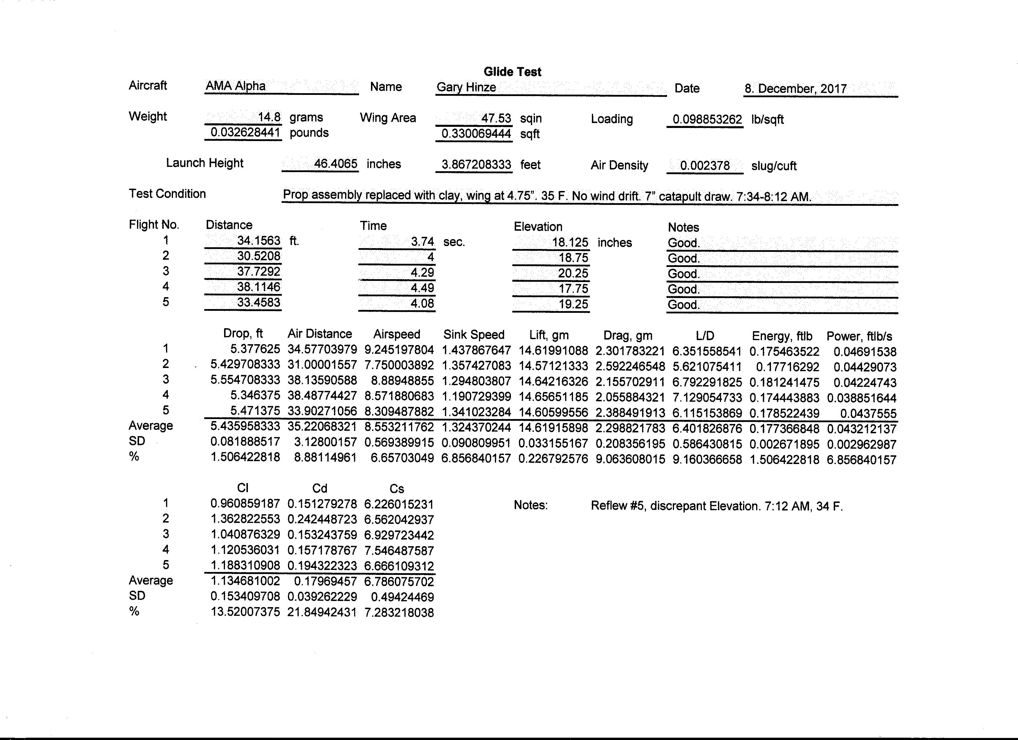
Glide test measurements are made with different wing positions to find the wing position that gives minimum sinking speed. It is necessary to measure height of descent, horizontal distance traveled and time of flight. Glides must be in a straight line and at a steady speed to produce valid results.
Launch catapult
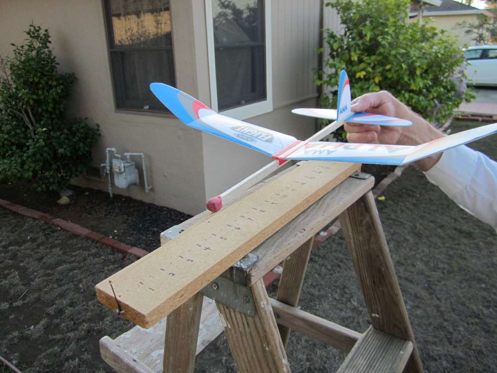
The original catapult launch platform was a small board with a block under one end to give it a slope. It was taped to the top of a ladder. There was a finishing nail just protruding from the low end, around which was fastened a 3″ x 1/16″ rubber band. A hook at the nose of the airplane was caught on the rubber band, which was stretched to catapult the glider across the yard. The problem with this was that parts of the airplane would rub on the launch board, interfering with the launch. The motor hook would catch on the rubber band. I put a pin shaft in front of the motor hook. Next I put the nail on top of the board. The tail plane would hit the nail, knocking the tail out of its slot. I needed a launch pin that would fold away. I made a loop in the end of a piece of wire and attached it to the end of the board with a construction staple. This proved too short and the plane still hit the board occasionally, resulting in irregular launches. I extended it to 2″ and it functioned adequately. I found that the board did not need to be sloped. The launch direction is controlled by the angle at which the airplane is pulled, the launch speed is controlled by the amount of stretch as indicated by the scale marked on top of the board. It takes practice to get uniform launches that produce straight, steady flights that do not display significant recovery. Each wing position has a different requirement for speed and angle.
leveling manometer
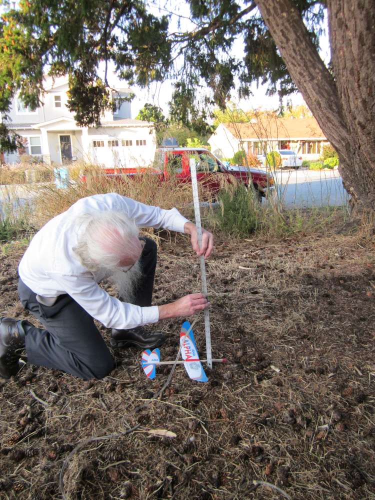
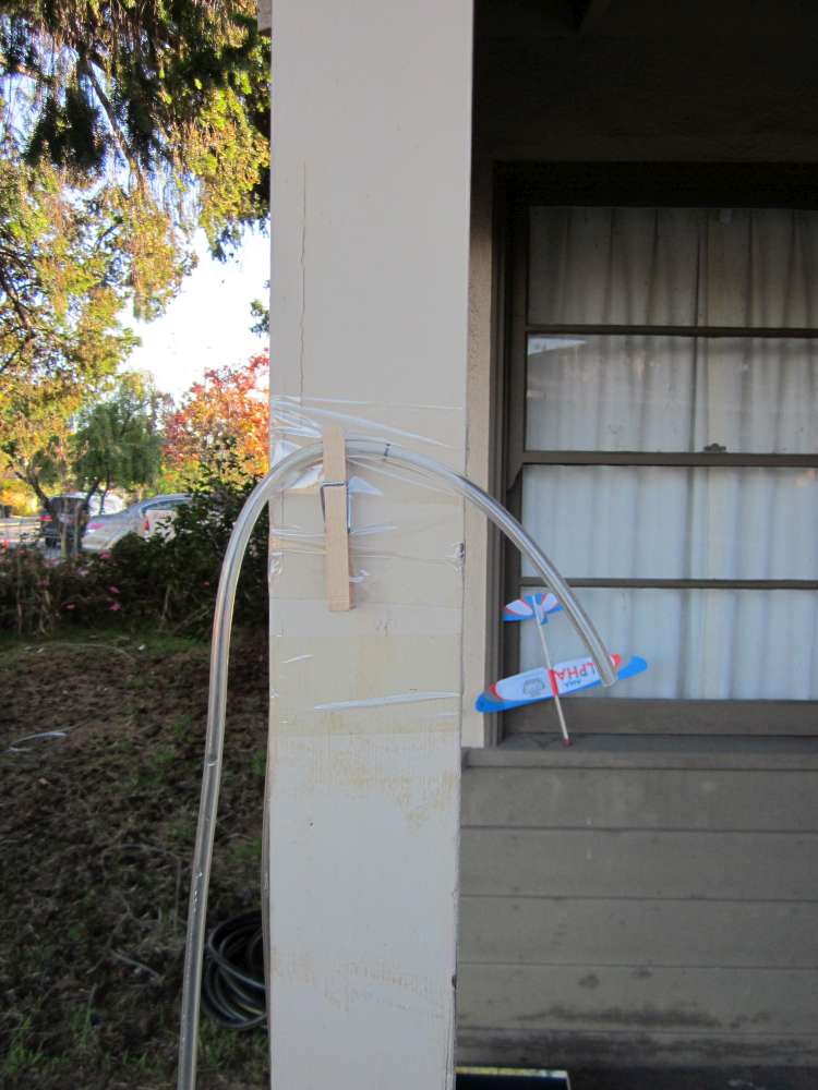
Although the yard looked level, I decided to check. I used water in a garden hose as a manometer. I found that the landing point elevations had a standard deviation of only 0.6″, but the feet of the ladder were about 4″ below the average. The fixed end of the hose was taped to a post. The reading end would be lowered until water appeared. The distance to ground would be measured with a yardstick. Unfortunately the water column would often have so much momentum that it would spill and the hose would have to be topped off and recalibrated. I chose a fixed point on the concrete driveway as a hard benchmark. The hose was also stiff and heavy. It had to be clamped to the ladder when not in use. I replaced it with 35′ of 1/4″ clear Vinyl tube. The surge was greatly diminished, but it was still difficult to get the water level and the end of the tube together. I taped a thread loop around the tube, 6″ from the end to use as the leveling point. The tape interfered with seeing the water. I marked a ring with indelible ink. The tube is overfilled with water. Water can be siphoned into the tube from a large jar. The indicating end of the tube is lowered to 18″ above the bench mark and the excess water is allowed to drain out. It is then raised to 30″ and the meniscus rises to 24″. The tube needs to be jiggled a bit to overcome surface tension and free the meniscus to move the last 1/4″ or so. This establishes a level datum plane. Whenever the meniscus is at the mark, it is at the same 24″ elevation above the bench mark.
The indicating end of the tube is held up by a clothes pin taped to the post between readings.
Drift detector
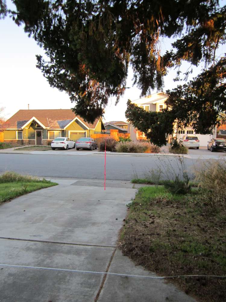
I had been using the tall grasses (in the background of a photo above) to detect air movement. They would move even sometimes when I couldn’t feel wind on my face. Nevertheless, there were flights when the plane would bob up and down irregularly, not with the regular period of a phugoid, indicating some turbulence. I needed a more sensitive drift detector. I added a loop of string to the end of a 75″ long, 1″ wide strip of crepe paper. The loop of string is tied to a twig on the tree with a Larks Head knot. This shows the slightest air movement.
I decided to redo all the glide tests for the sake of consistency. Unfortunately my new drift detector tells me there is almost no time when there is no drift. We even had a series of wind storms. The weather forecast usually shows least wind at night. I have been out in the dark with a flashlight in my mouth making measurements.
glide test spreadsheet modifications
powered flight testing
Since completion of the glide test program was being delayed, I decided to build another AMA Alpha for the power tests. This entails winding the motor to 600, 800 and 1,000 turns and recording the flight times. At 600 turns, it makes a short descent. At 800, it goes a little farther, going down the whole way. At 1,000, it goes about a half circle. It may go up slightly at the beginning with a fast launch. I was going to try 1,200 turns, but the wind had picked up. The recent wind has prevented further trials. The motor has a capacity of 1,400 turns, so we can’t go much further. It may be better to use 1/8″ rubber strip for this, rather than the 3/32″ supplied.
