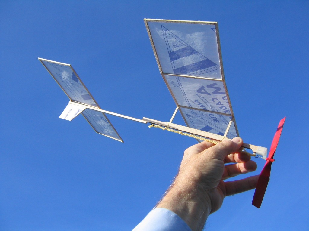
In our model airplane class, we first taught every kid to build and fly an AMA Cub, a Dandiflyer and an EZ Penny Pennyplane. We had contests for each type, and one called Delta Dart Own Design (DDOD), in which the kids designed, built and flew a plane made entirely from the materials in an AMA Cub kit. One of the boys had made an EZ Penny. Seeing that it was an excellent duration flyer, he patterned his DDOD after the Pennyplane. It flew quite well and won the contest.
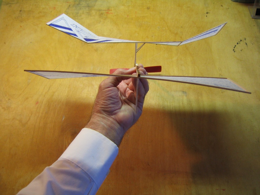
The distinctive features of this plane are the relatively high aspect ratio rectangular wing, the flat center section with angled up wingtips (polyhedral), the uncambered (flat) airfoil, the wing mounted high on posts, the separate motor stick and tail boom and the sub fin.
There is not quite enough paper in the AMA Cub kit to make a full size Pennyplane. The Pennyplane has an 18″ wingspan. The Cub paper is 14″ long. The simplest AMA Cub Pennyplane is scaled down to a 14″ wingspan. (By cutting and splicing several pieces, it is possible to make a wing covering 15 9/16″ long.) I have scaled the principal dimensions of the 18″ EZ Penny to a 14″ wingspan for this model.
Although the Pennyplane made from the AMA Cub kit might qualify under the rules of the Pennyplane event, it is nowhere near competitive. It will weigh much more, have much less lifting surface and a smaller diameter propeller than a competitive Pennyplane. It will be competitive in a DDOD contest. Groups could sponsor a contest just for Pennyplanes made from an AMA Cub kit, or copy this one for a one-design contest.
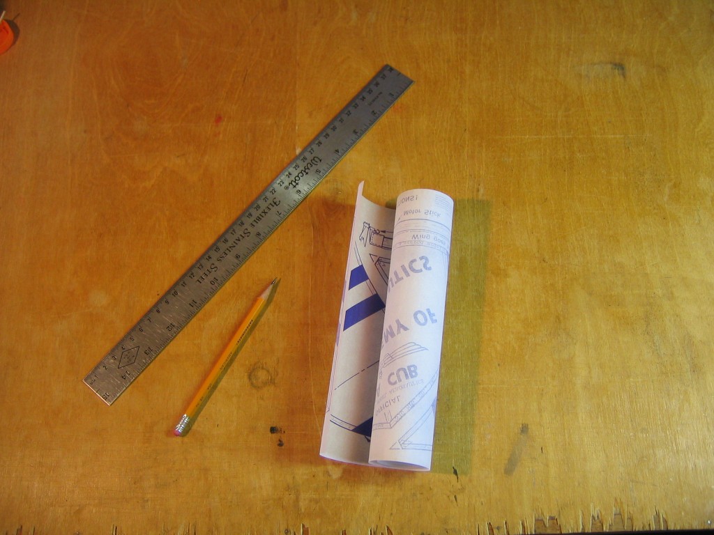
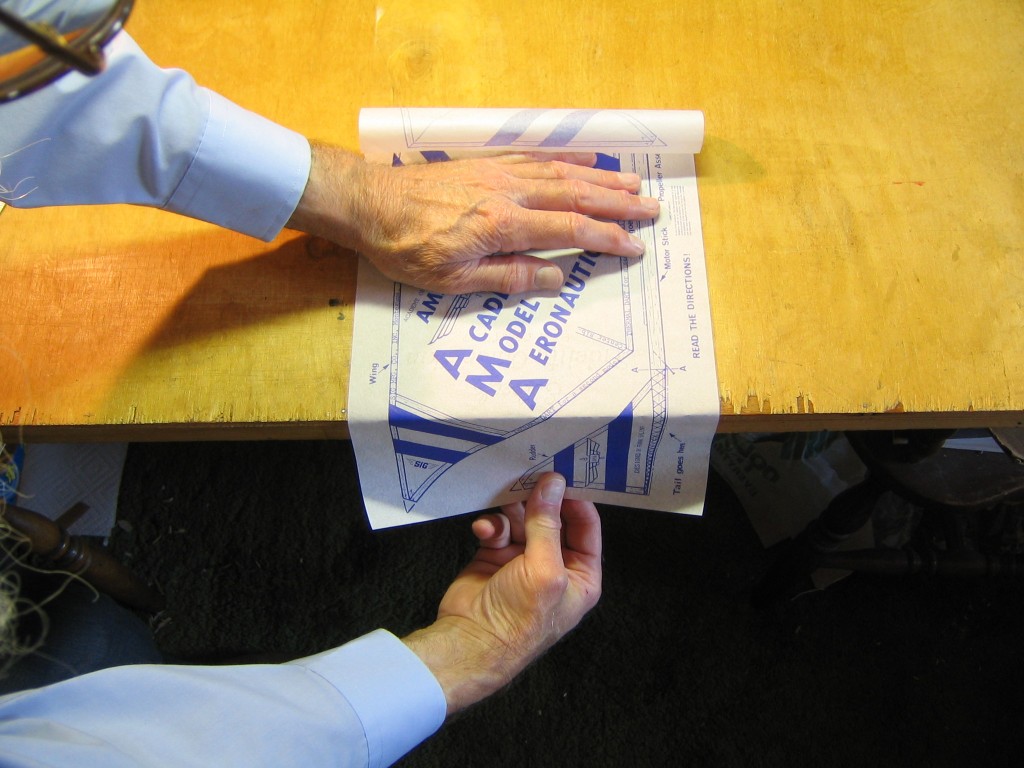
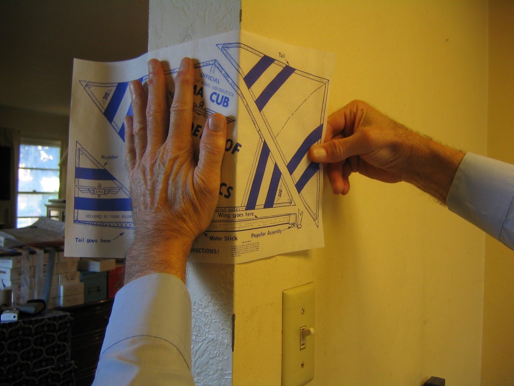
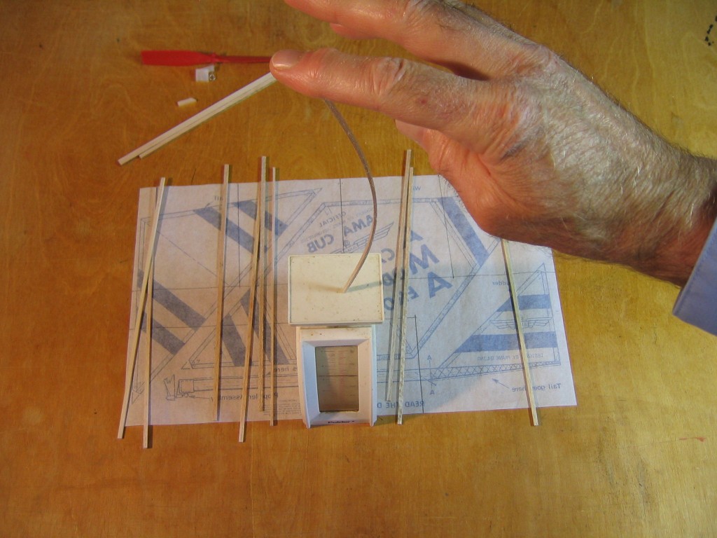
The paper comes tightly rolled from the kit. It is easier to work with if it is straightened first.
It can be straightened by pulling it over the edge of a table,
or around the corner of a wall.
Start by measuring the length of the long side. It is nominally 14″. The paper will expand in humid air and contract in dry air. If you build your plane in humid air and fly it in dry air, or in bright sun, the paper will contract and pull on the sticks, bending the wing and tail. The plane won’t fly.
This plane was built on a foggy day. Even though it was warmer and dryer in the house where it was built, the paper shrunk and badly warped the surfaces when the weather changed.
I find that this will happen even if you preshrink and crumple the paper. It is best to build the plane when the paper is less than 14″ long. Preferably, the relative humidity should be around 50% or less and the paper should be 13 15/16″ or less. Wait for a dry day, or increase the heat in your work room. Temporarily heating the paper will not work. It will respond to humidity changes within a couple minutes.
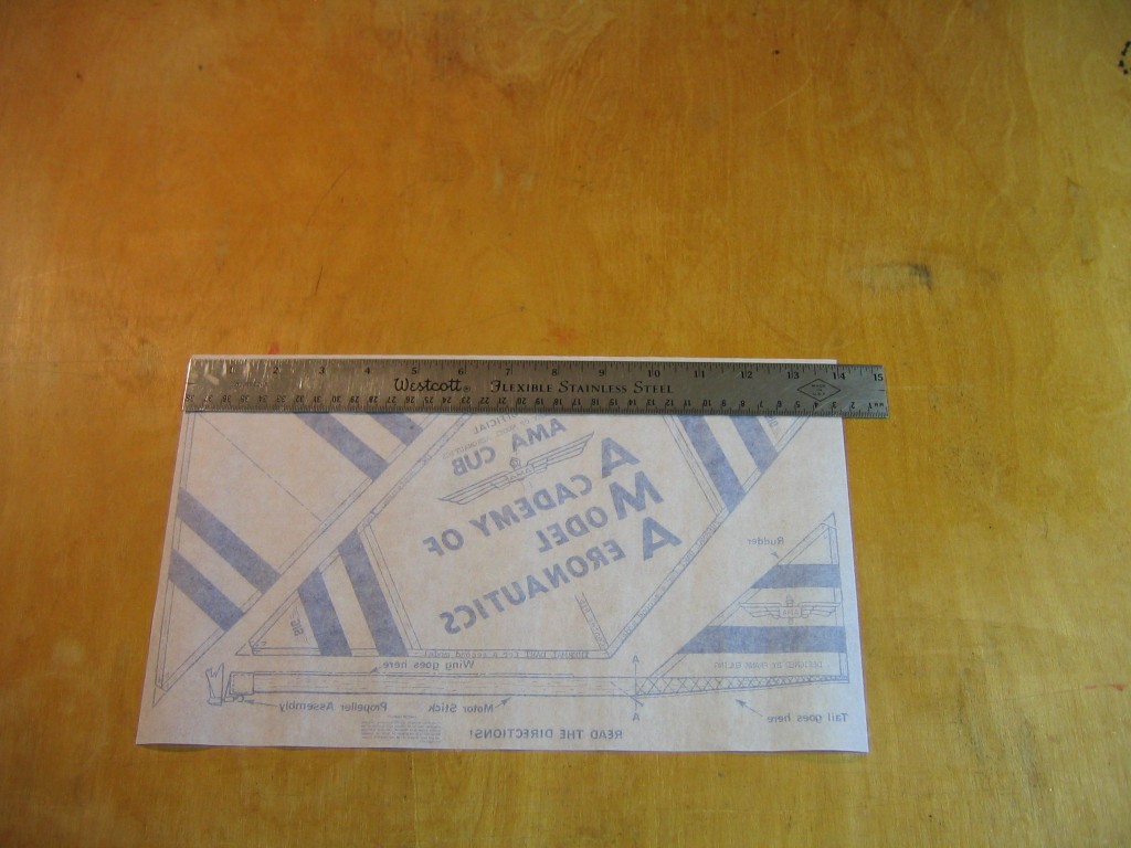
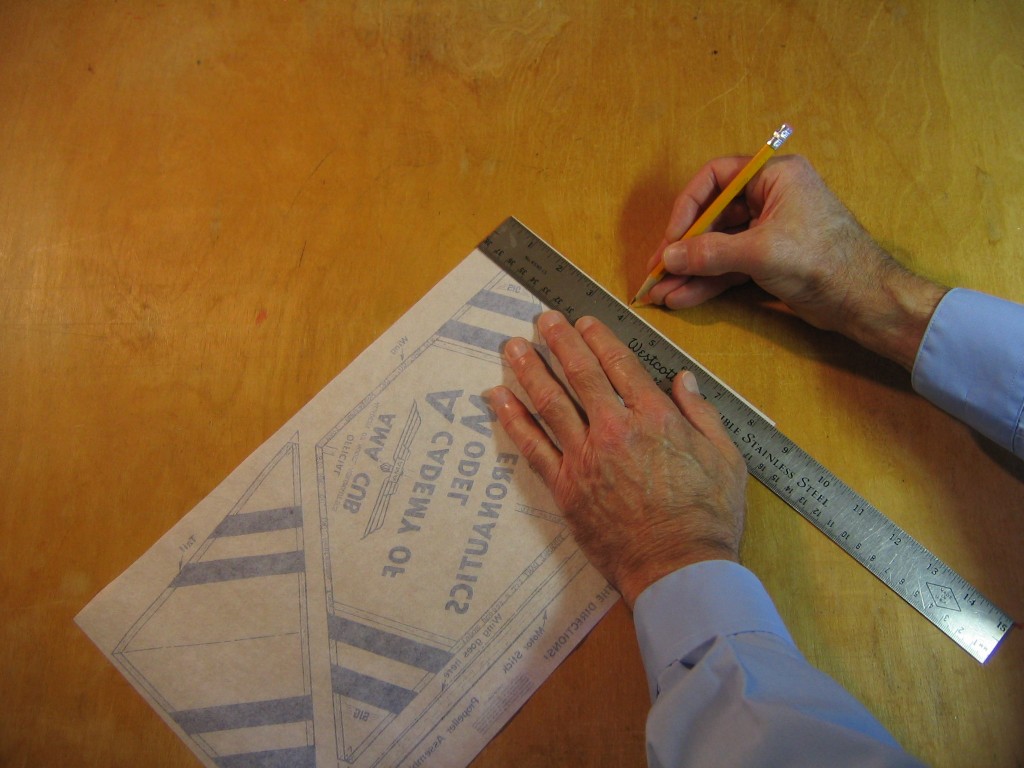
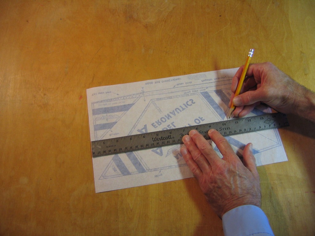
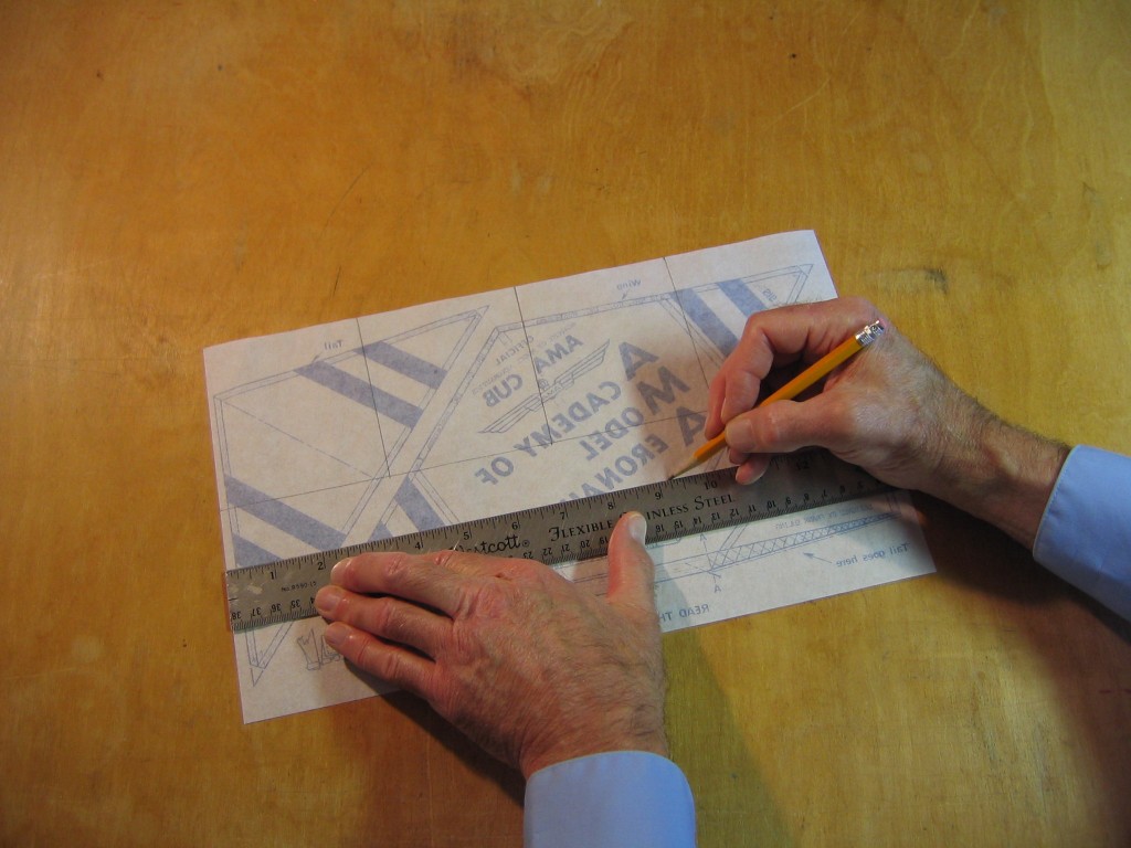
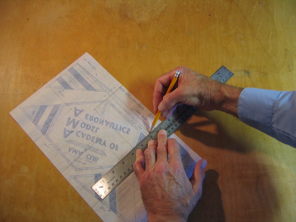
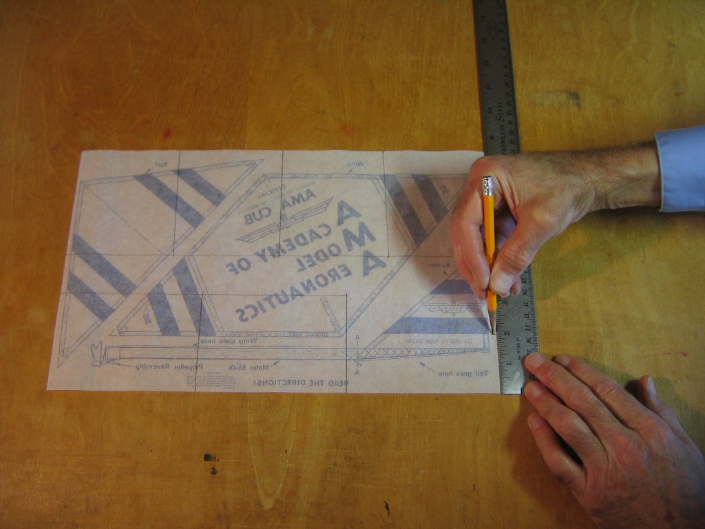
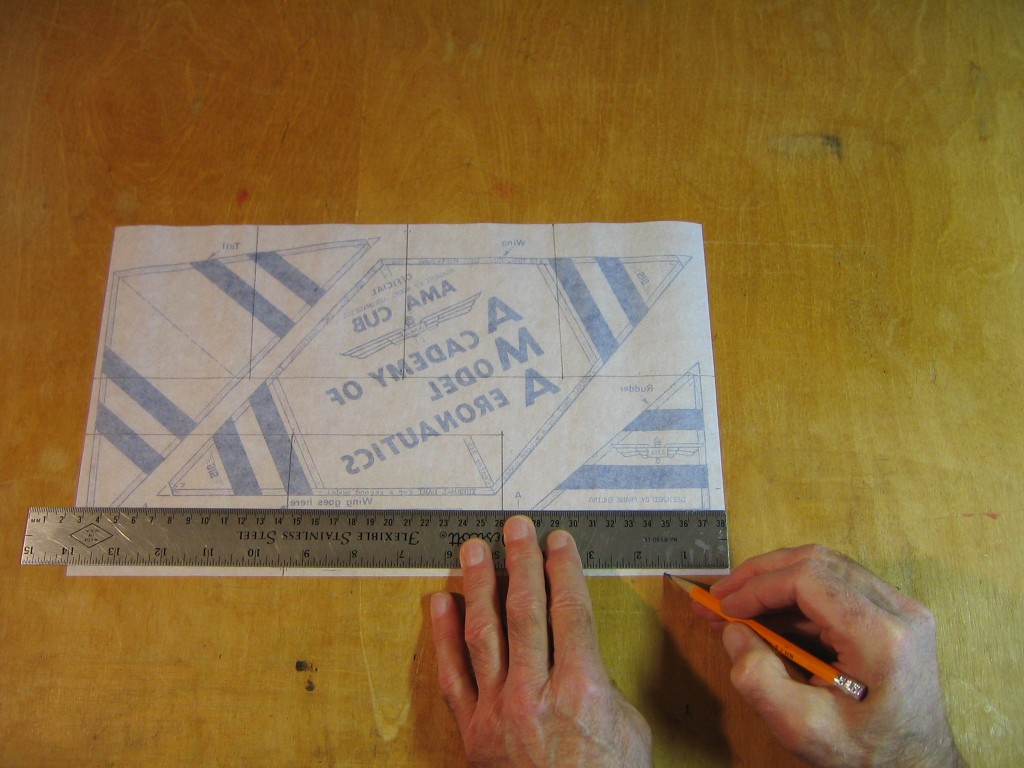
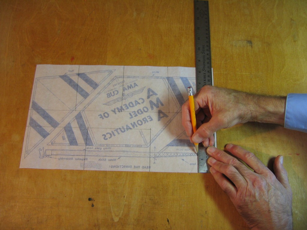
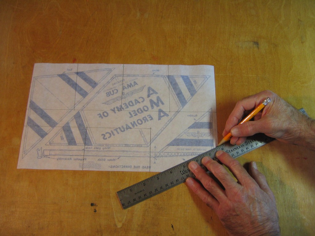
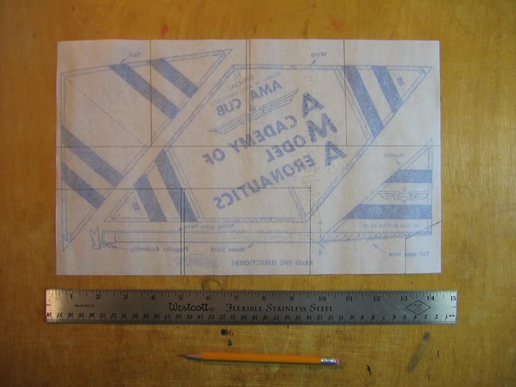
Like the AMA Cub, the sticks will be glued directly to the paper. Since the Pennyplane does not conform to the original AMA Cub plan, new lines must first be drawn on the paper. Put the paper on the table with the ink side down. We will mark the underside of the paper and glue the sticks to the same side as the marks. Mark the wing chord 3 7/8″ along each 8 1/2″ side to mark out the rectangular wing. The wing marked out here will have the AMA Cub logo on it.
Draw the edge of the rectangular wing. Mark the location for the three wing ribs. One rib will be exactly on the centerline. Mark the exact center of the wing and 1/16″ on either side of that mark, to locate the 1/8″ wide center rib.
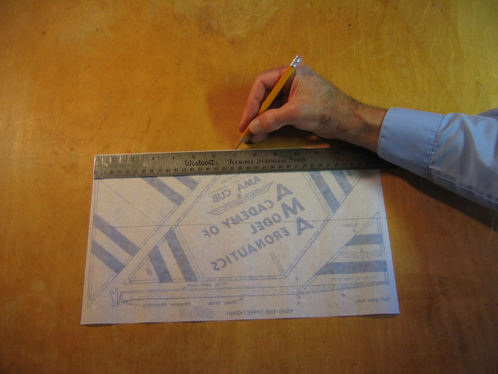
The other two ribs will be at the dihedral breaks. These two will be angled slightly to balance the roll from motor torque in flight. The mark on the right of the leading edge shown here is 3 1/2″ from the centerline. The mark on the left will be 3 9/16″ from the centerline.
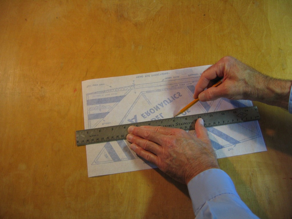
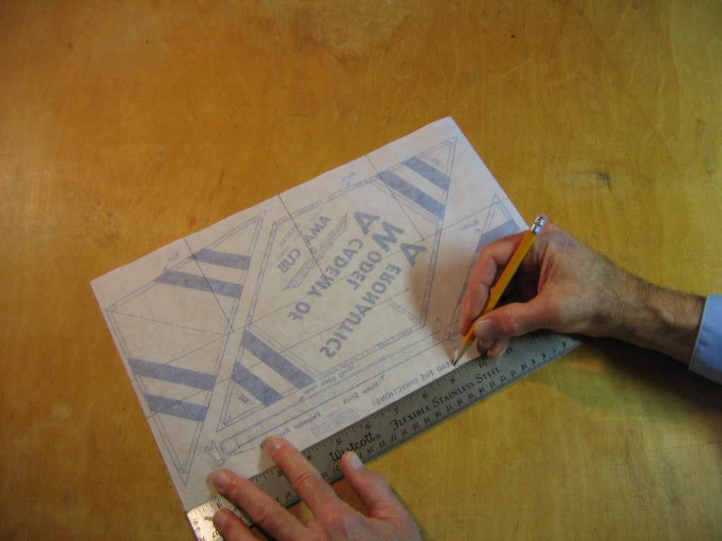
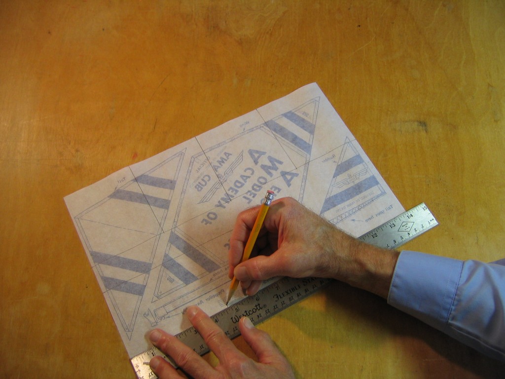
Make the corresponding marks on the trailing edge. Mark the exact center of the wing and 1/16″ on either side of that mark, to locate the 1/8″ wide center rib. Because I have turned the wing around, the mark on the right is again 3 1/2″ from the centerline and the mark on the left will be 3 9/16″ from the centerline.
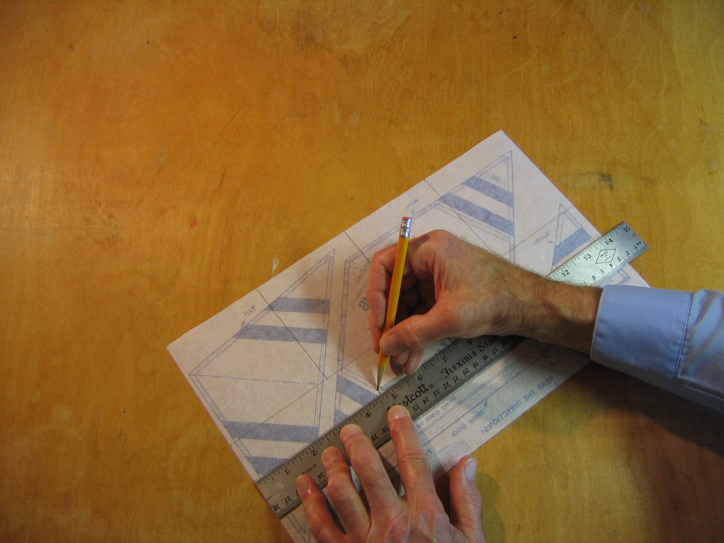
Connect the corresponding points on the leading and trailing edges. There will be two lines connecting the points corresponding to either side of the center rib, but the dihedral break ribs can be located by a single line. The ribs will be glued to the paper inside these lines.
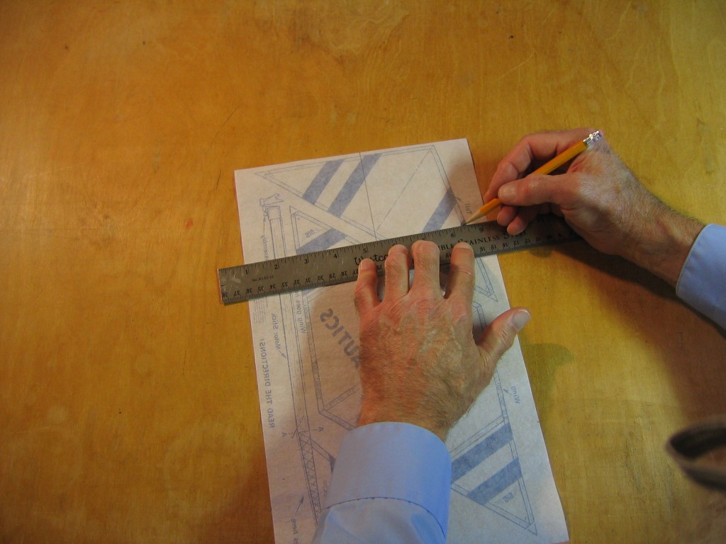
As with the wing, mark the 3 1/8″ tailplane chord along each 8 1/2″ edge of the paper.
Mark the tailplane span at 9 1/4″. The sticks in the AMA Cub kit are 9″ long and the two 1/8″ wingtip ribs add another 1/4″.
Mark the 9 1/4″ tailplane span on the other edge.
Mark the centerline at 4 5/8″ and put a mark 1/16″ on either side of it.
Do the same on the other edge.
Connect the dots to draw the tailplane tip and two lines for the edges of the center rib.
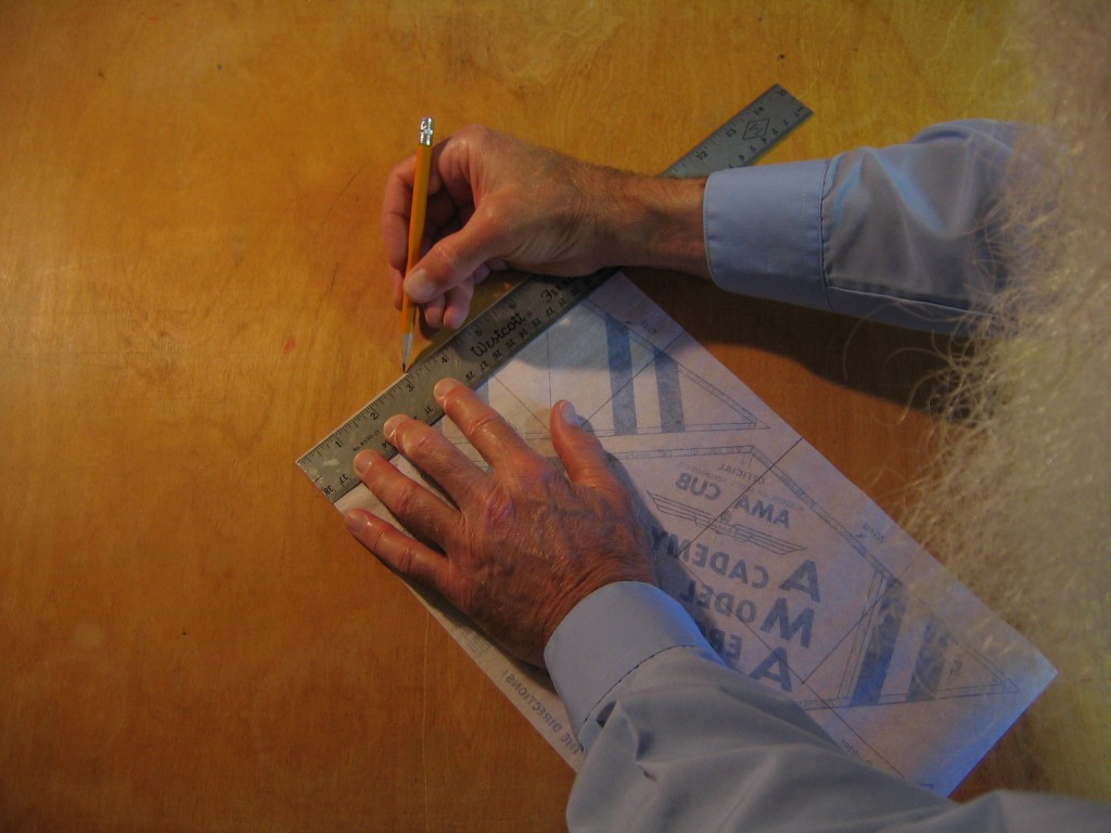
Mark the fin root chord 1 7/8″ from the free corner along the 8 1/2″ side.
Mark the fin span 1 3/8″ from the corner along the 14″ side.
Draw the 1 1/4″ tip chord parallel with the 8 1/2″ side of the paper.
Draw in the leading edge of the fin.
This completes the drawing of the lines on the paper. You could make a copy of this on 11″ x 17″ paper to use as a plan for building more of these planes.
If you want to lead a group building AMA Cub Pennyplanes, I suggest making such a drawing on an 11″ x 17″ sheet and giving a copy to each builder to use as a plan. The plan can be taped to a building board, covered with a transparent protective sheet and the AMA Cub paper can be taped over the plan. This will make the build much faster than having everyone draw the lines on their paper. (One problem I can see with this is shrinking paper not fitting the plan. It might be necessary to cut out the pieces and center each of them seperately over the appropriate part of the plan. Losing a little equally off each wingtip is better than having the paper off center. The paper for the fin and tailplane should be able to cover the whole plan drawing.)
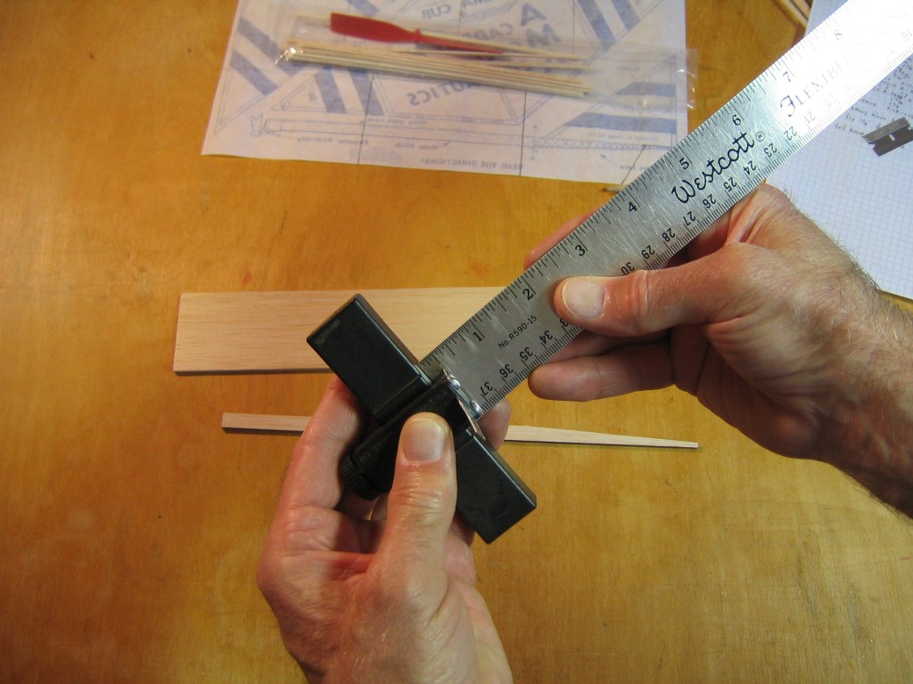
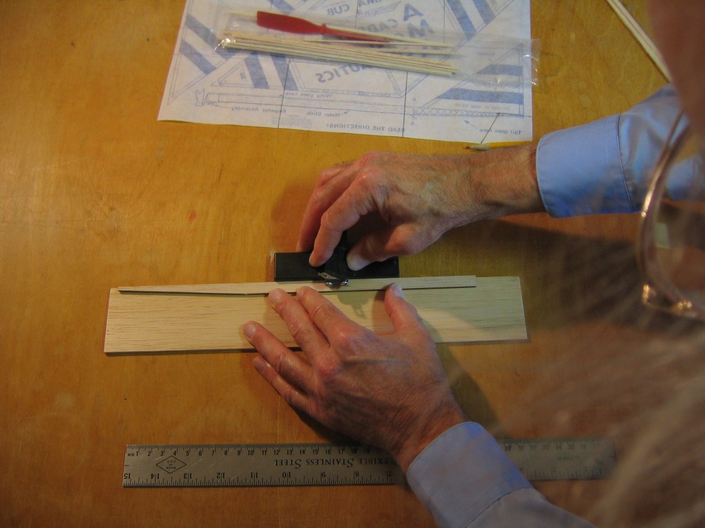
We will cut the 3/8″ wide AMA Cub stick into two parts, one 1/4″ wide for our motor stick and one 1/8″ wide for the tail boom. Set the balsa stripper to cut 1/4″ wide.
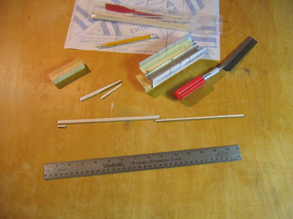
Cut the motor stick from the longer edge of the stick, leaving the shorter offcut for the tail boom.
Mark the 8 5/32″ motor stick length on the 1/4″ wide stick.
Mark the 7 5/32″ length of the tail boom on the 1/8″ wide stick.
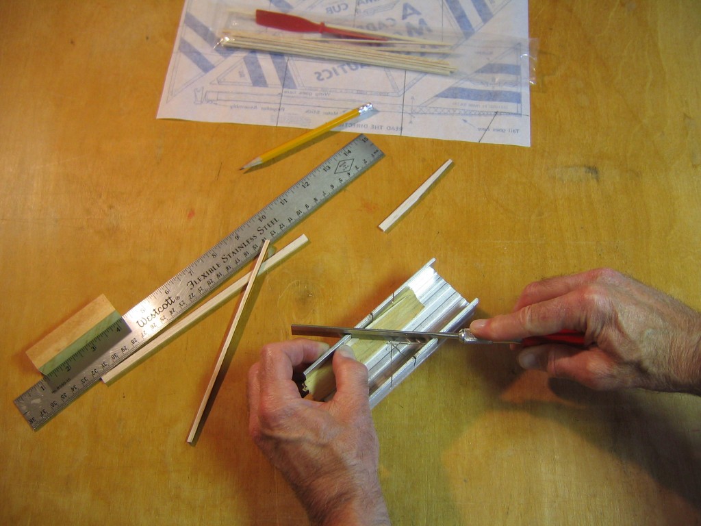
Cut the motor stick to length at the mark. This can be done with a razor blade if you do not have a fine saw. Make several cuts with the point, rather than trying to cut it all at once.
Cut the tail boom to length at the mark.
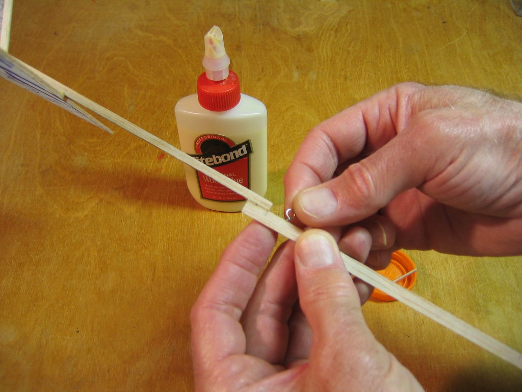
The 3/8″ opening in the propeller hanger will not be a snug fit on the 1/4″ motor stick. We must glue a nose block on the motor stick to make the front end 3/8″ wide. Cut a 5/8″ length from the remaining 1/8″ wide stick. I cut the end with a 45 degree taper.
Here are the three pieces of the fuselage. I balanced the motor stick and tail boom, and put the heavier end to the front.
Test the sticks for stiffness and sort them into piles. You can gently bend them in your fingers, just enough to feel their stiffness, being careful to not break them. It is fairly easy to sort them into three piles; stiff, medium and soft. The scale allows me to sort them into 5 or 6 piles.
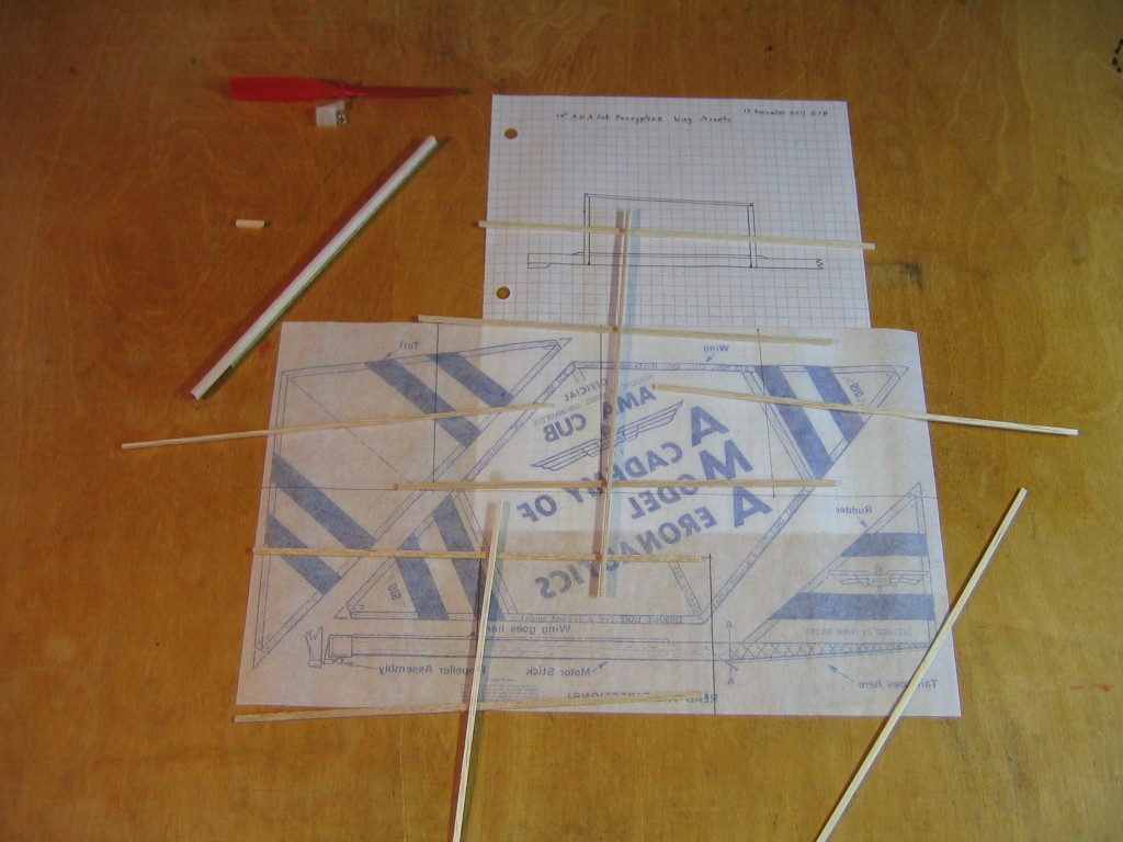
Place the sticks where they will go on the plan. Use the stiffest sticks for the center part of the leading and trailing edges of the wing and for the leading and trailing edges of the tailplane. Save the cutoffs for the wing posts. Use the softest wood for the fin. Use the medium wood everywhere else. Wood is chosen to put the stiffer pieces where greater strength is required, and the heavier pieces closer to the front, consistent with strength requirements.
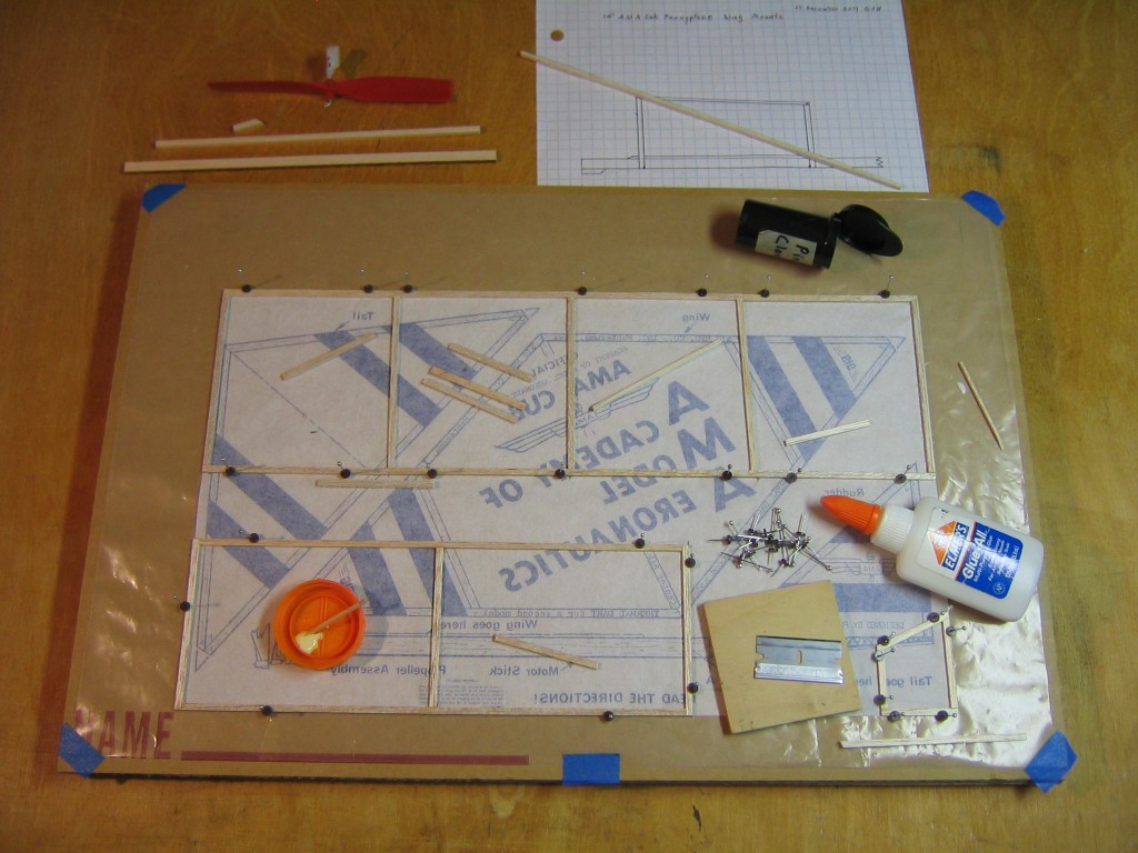
Construction is very similar to the other planes made from the AMA Cub kit. The wing leading and trailing edges are in three parts, to allow the wingtips to be bent up to form the dihedral angles. I glued the sticks to the paper with Elmer’s and I glued the wood to wood joints with Titebond. Other suitable glues for wood and paper may be used. Note that the intermediate wing ribs are glued between the leading and trailing edges of the center section. They go inside the drawn lines. These are cut at a slight angle. The tips of the leading and trailing edges are seperate pieces and they are not glued to the center sections, to allow the tips to be raised to form the dihedral angles.
While the wings are drying, we can build the fusealge and wing post assembly.
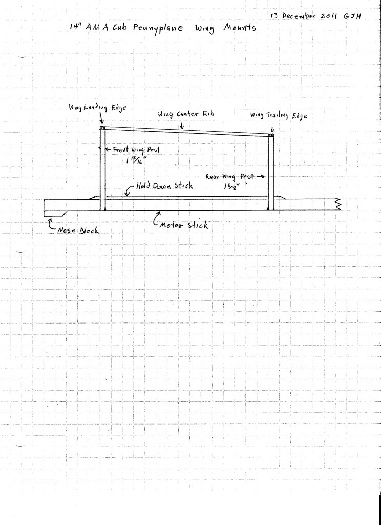
The wing posts are attached to a hold down stick that is attached to the motor stick with dental elastics. This allows us to adjust the wing position for correct balance. Copy and print this plan. The wing chord is 3 7/8″. Tape the plan to your building board and cover it with a transparent protective sheet.
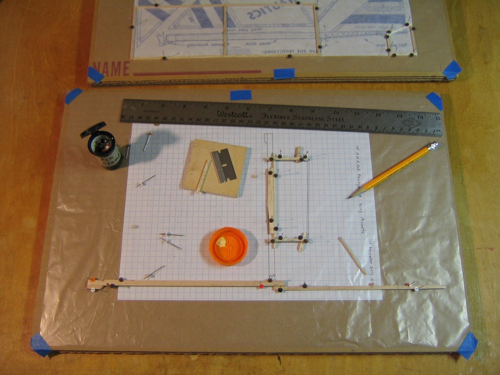
The wing post assembly consists of three parts: the hold down stick and two posts. Cut them to match the plan. The top of each post is cut with a slight angle. Use bits of scrap wood and pin clamps to jig them in place while the glue dries. It is important that the hold down stick is perpendicular to the board and to the posts, and the posts should be parallel with the board. At the same time, pin down the motor stick and glue the noseblock and tail boom to it. The motor stick and tail boom overlap 3/8″. The bottom of the motor stick and the top of the tail boom are on a straight line.
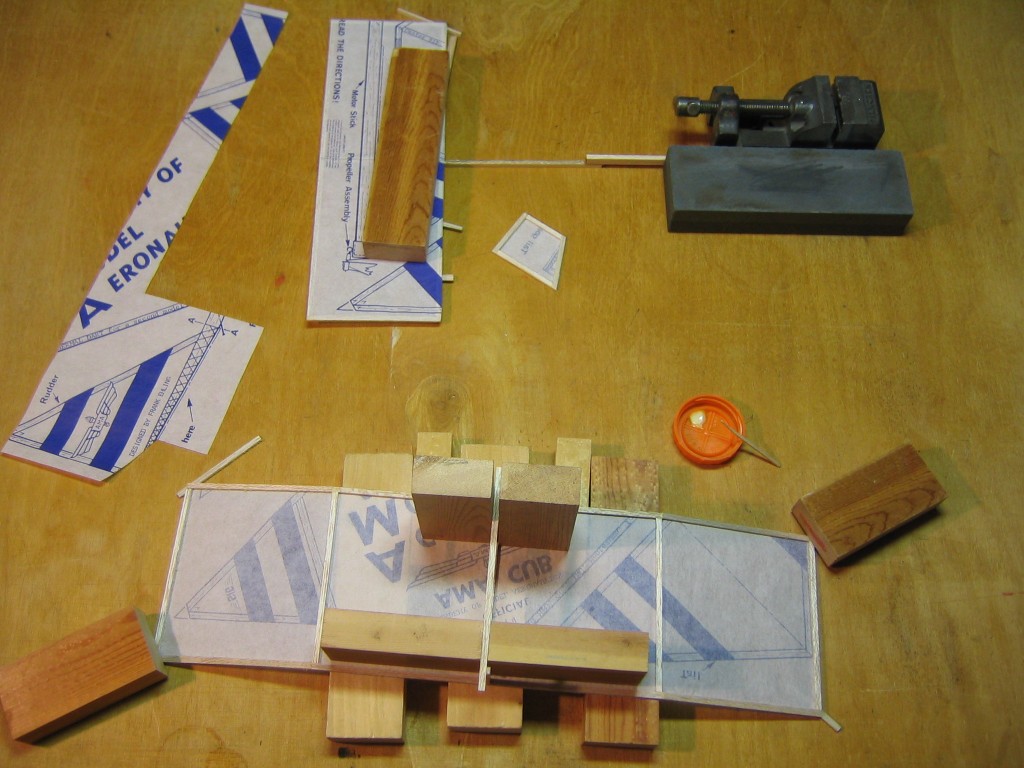
Once the glue is dry on the wings, cut them out from the paper. Support the wing upside down on some 3/4″ blocks. Bend the tips down and fill in the gaps with glue. Hold the tips down with weights, but shim the tips of the shorter leading or trailing edges up with scrap sticks. Glue the wing post assembly to the center of the wing. The hold down stick should be directly over the center rib. The top ends of the posts will be offset 1/16″ from the centerline. Jig the post assembly so it is perpendicular to the wing. Check everything before you let the glue dry. A little fillet of glue around the joints will strengthen them.
Jig the motor stick so it is upright and perpendicular to the table top. Here I have used the machinists vise and sharpening stone to hold it in place. Apply glue to the leading and trailing edges of the tailplane at the center. Jig the tail plane in place on the tail boom with scrap wood. Lightly weight it to hold it down flat. There is a 1/16″ x 1/16″ x 1/8″ shim under the trailing edge of the tailplane, as on the AMA Cub, only this time it raises the trailing edge, because it is on top of the stick.
Glue the fin to the underside of the tail boom, angled to produce a left turn. The paper will be on the right side of the fin when the structure is turned right side up. The fin will be under the tailplane.
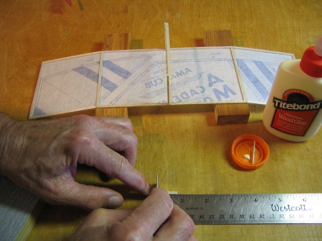
Cut a 3/4″ length from a piece of scrap.
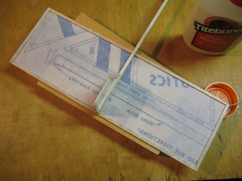
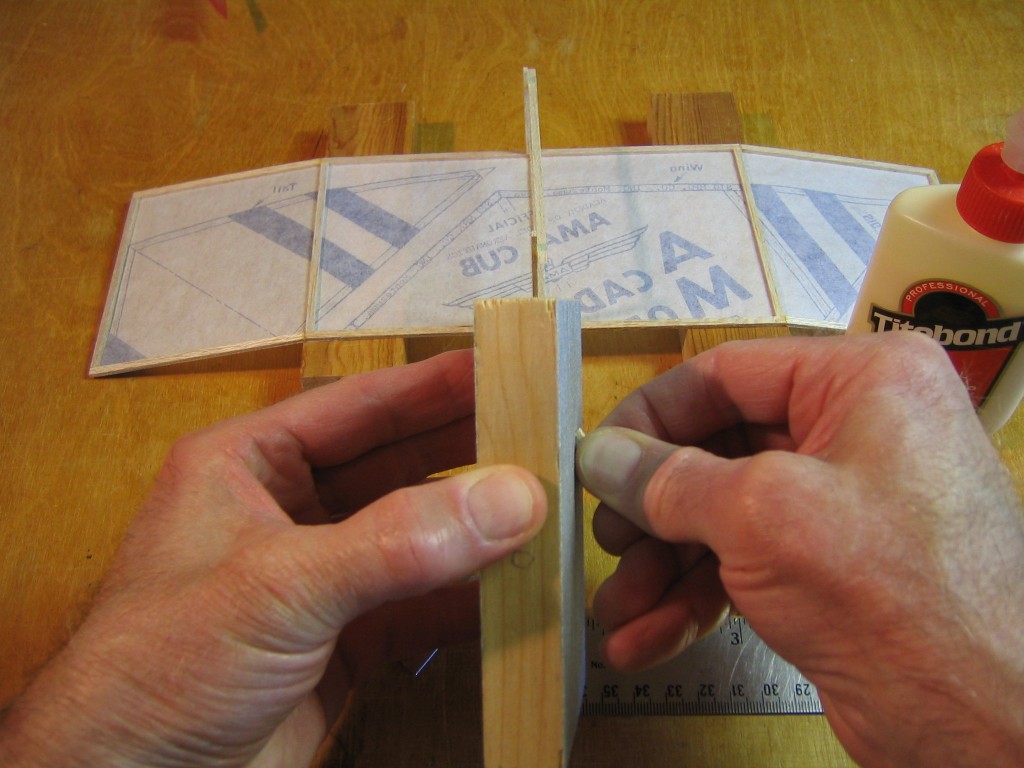
Sand the ends to a 45 degree bevel.
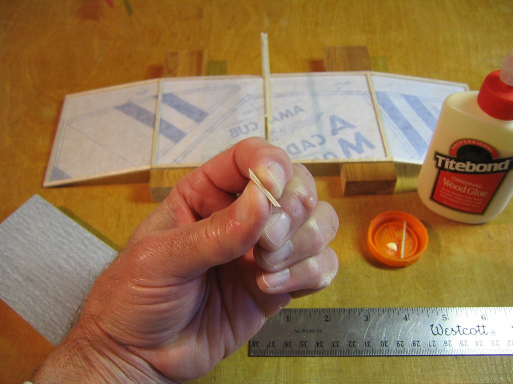
Sand both ends on the same side to look like this.
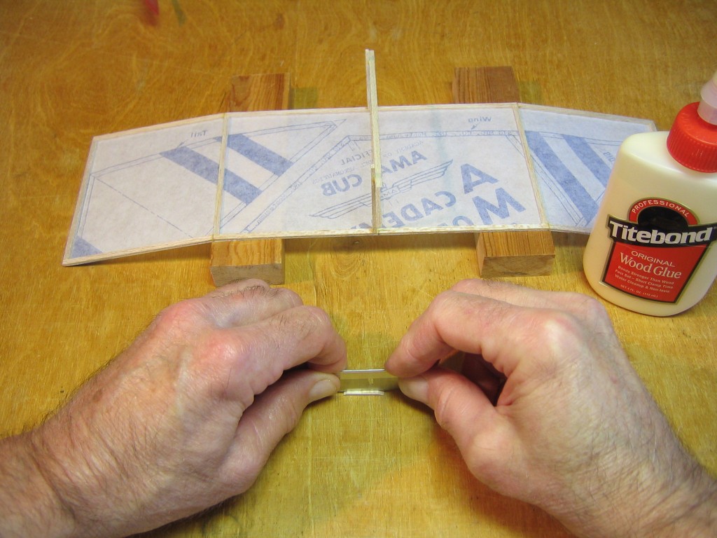
Cut this piece exactly in half to make two equal 1/16″ square pieces.
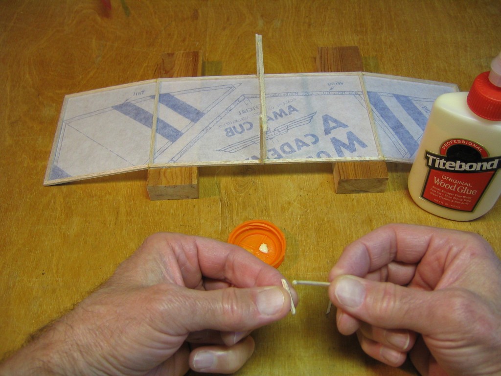
Apply glue to both beveled faces.
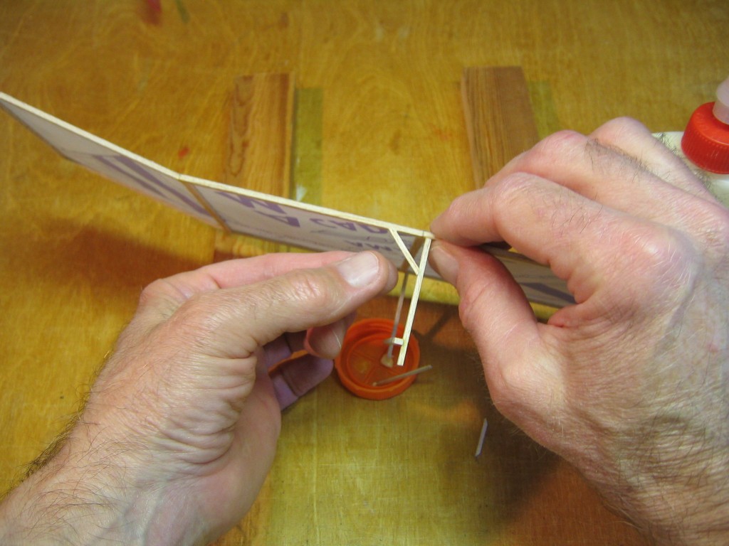
Place the braces between the wing posts and the wing spars. Place them on the side between the wing rib and the hold down stick. Be sure the angle between the post and wing spar stays square.
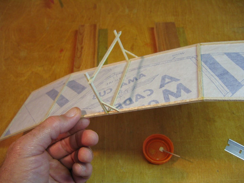
Both braces are in place. Without this brace, the wing is easily knocked loose in collisions.
Make a rear motor hook from a pin and install it, as was done in the AMA Cub Master Class.
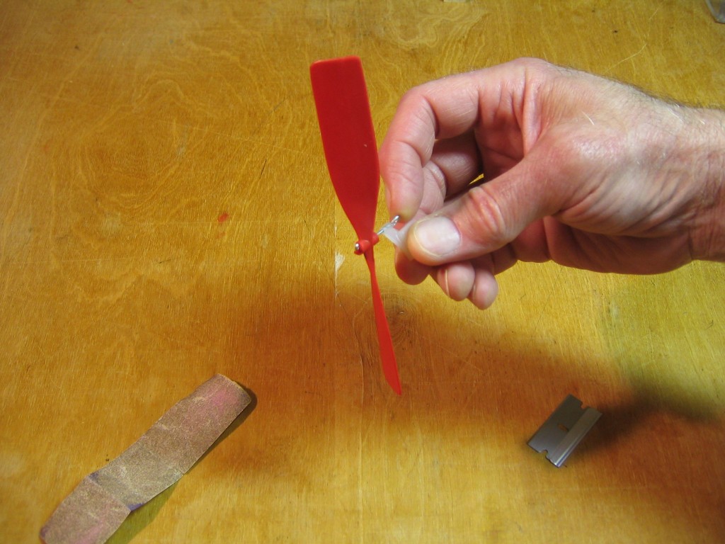
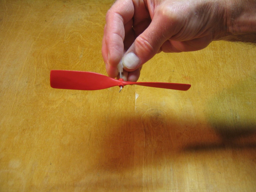
Push the prop shaft forward and let the prop swing freely. The heavy blade will swing down.
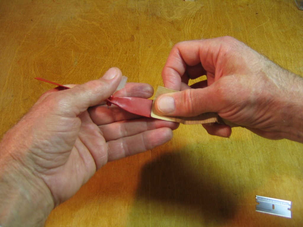
If the prop is badly out of balance, use sandpaper to remove plastic from the heavy blade. Check frequently to see how close it is to balancing.
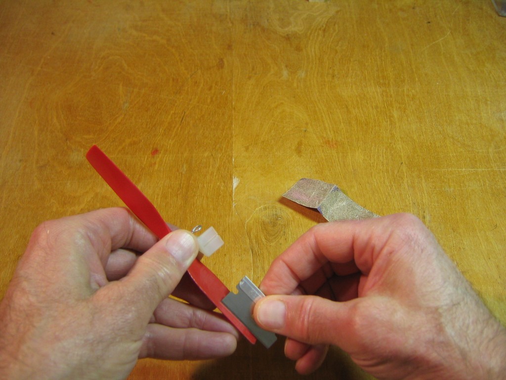
When it is close to balanced, or if it was not much out of balance to start with, finish smothing and fine balancing by scraping with a razor blade. Be very careful not to cut your fingers, working close to the razor blade. Keep them away from the direction the razor blade is moving. Protect them with the propeller blade.
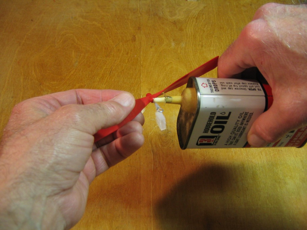
Put a small drop of light machine oil on the prop shaft, between the prop and bearing.
When properly balanced, the prop will stay in a horizontal position.
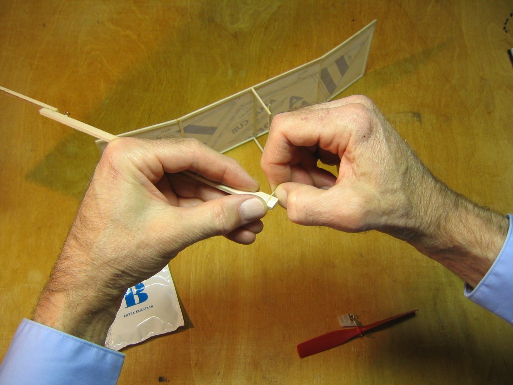
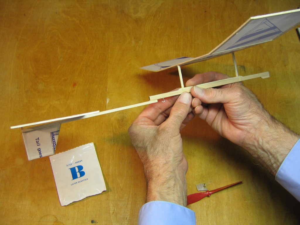
Put small dental elastics around the stick. I found that two were needed at each end of the hold down stick. Slide them into approximate position.
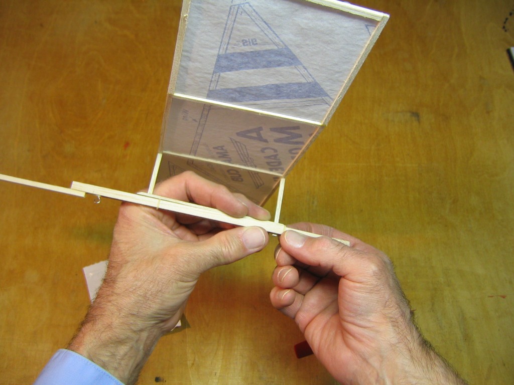
Roll the elastics up the beveled end of the hold down stick.
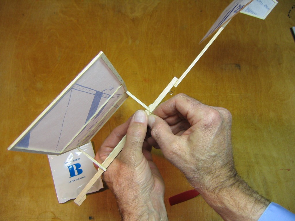
Do the same at the back end of the hold down stick.
Loop the elastics around the bases of the posts to hold them securely against the sides of the motor stick.
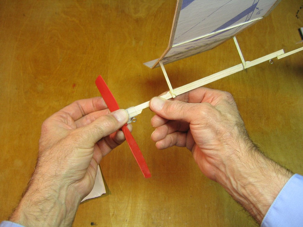
Slip the propeller bearing over the end of the motor stick, with the propeller hook down, on the same side of the stick as the rear hook.
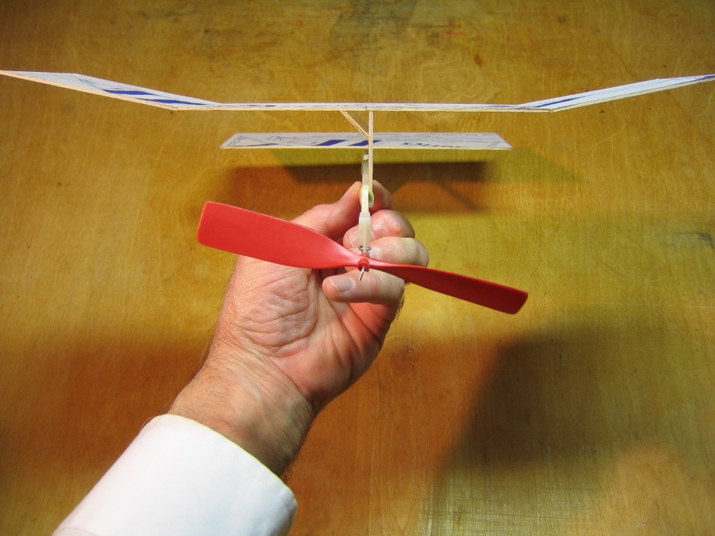
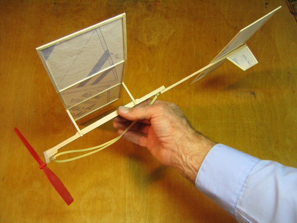
Check that everything is square and true. If anything is out of line, fix it. The finished plane weighed 9.9 grams.
You can use the motor that comes in the AMA Cub kit, but it is too wide for best flights. You won’t be able to wind it up much without causing torque problems and there won’t be many turns for flying.
I started flying with a 12″ loop of 3/32″ rubber strip. This is longer than the 7″ distance between the hooks.
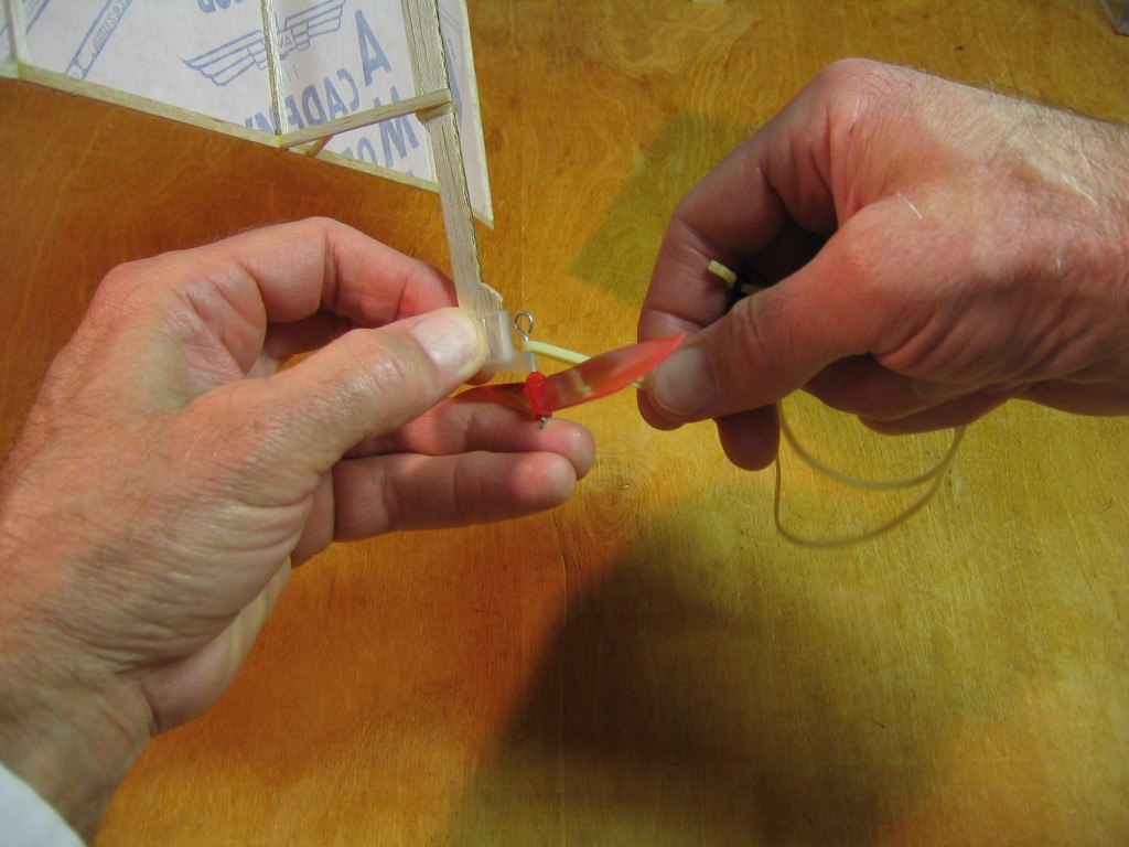
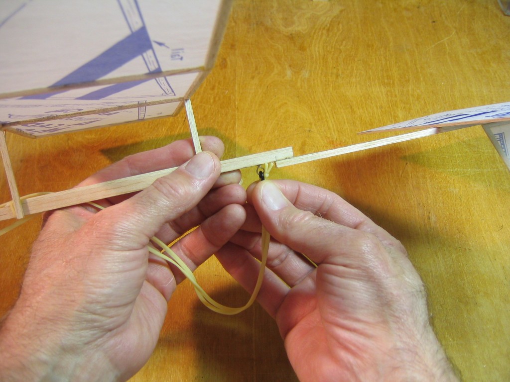
It is easiest to wind an overlong motor with a mechanical winder. Especially considering how many turns we will be putting into this motor. I started test flights with 1,200 turns. An O-ring at the back end facilitates the use of a mechanical winder.
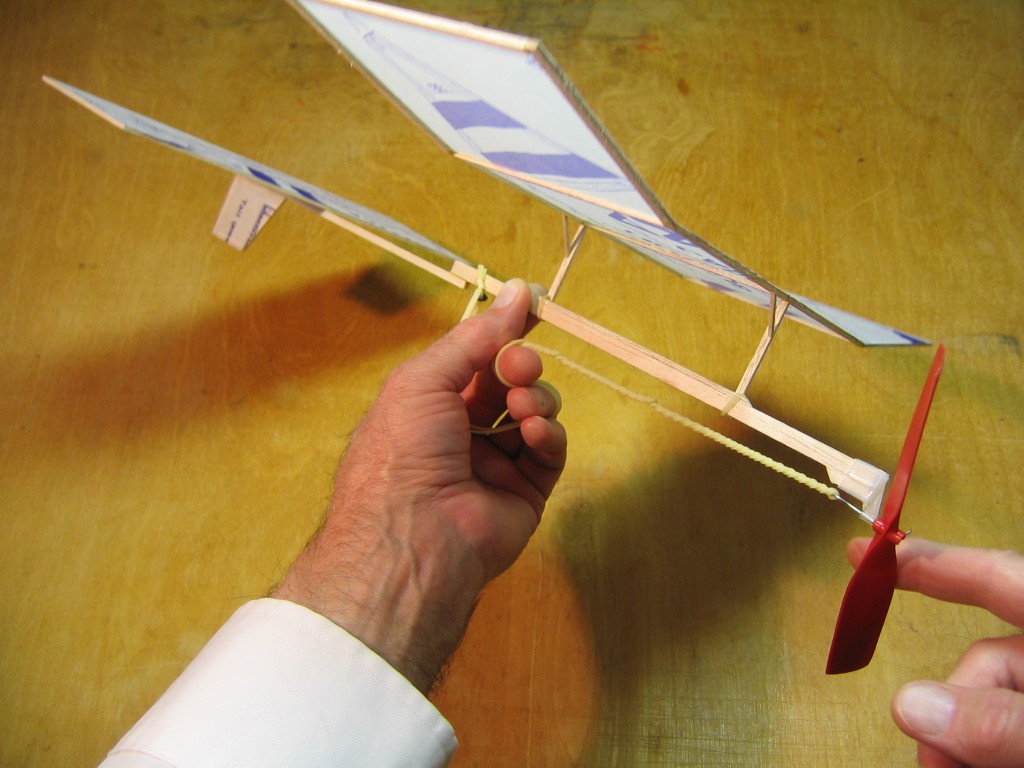
You can finger wind an overlong motor by threading it around your fingers and letting the winding gradually take up the slack.
Take it over to the park and fly it! You can start with around 900 turns. Adjust the wing position until you get good flights. If it noses down, move the wing forward. If it noses up and drops, move the wing back. Then you can try more turns.
Turns table for 12″ loop of 3/32″ rubber, with breaking turns 119.9 turns per inch.
100% 1,438
95 1,367
90 1,295
85 1,223
80 1,151
75 1,079
70 1,007
65 935
60 863
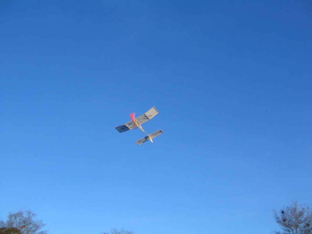
This is the larger of two AMA Cub Pennyplane designs that I have built. It has a 15 9/16″ wingspan and weighs 8 grams. I used 1/16″ square sticks, cutting the kit sticks in half. Here it is flying on a 10 1/2″ loop of 3/32″ rubber strip with 700 turns. This is not the best motor, but I want to limit the flights in this small park to keep the airplane out of the trees. This is just a short test flight to check climb and turn. Notice that the motor runs out of turns while the plane is still in the air.
–
My son is interested in building a penny plane. Is there a website that sells starter kits you can direct us too?
Thank you so much for your help!
Susie
Hi Susie,
None of the manufacturers of Pennyplane kits are still in business. Micro-X, Lee’s Hobbies, Indoor Model Supply and Indoor Duration are gone. You might be able to find one on eBay.
IKARA makes a model that is prefabricated. Their web site lists sellers.
Alternatively, he can build his own from scratch. There are many resources on the Internet.
Ron William’s book is the best guide in print.
You may be able to find a copy of Lew Gitlow’s Indoor Flying Models online. It is out of print.
John Barker’s build is online.
Hepcat posted his build as a blog.
Ben Saks posted his build as a video.
Here is a blog about building the IMS Time Machine.
Your son will need a large indoor space in which to fly a Pennyplane. It would be good if he could find a nearby club that flys indoor models. The National Free Flight Society links page includes a list of clubs. He would also get guidance from members of an indoor club.
You can find resources for materials and tools online, too, such as Ray Harlan and FAI Model Supply.
Gary
Hi Susie,
Blue Ridge Models has just resumed production of an indoor kit, the Little Zephyr. Click on the link to see the description and order kits. This is not a Pennyplane, but it uses similar materials and techniques. It would be good practice for someone who has never built an indoor model before. It has an 11 1/2″ wingspan and includes materials to build two planes. One can be built according to the plan. You can try changes and more advanced techniques with the second one. One change I would recommend is in the propellers. These propeller blades are made flat. Propeller blades work better with some twist. This is usually done by soaking the thin sheet balsa propeller blades in water, blotting them dry and strapping them to a can at an angle, 15 to 20 degrees, with cloth strips to hold them in place until they dry. This will put some twist into the blades, and also some camber. It is also good to be able to adjust the angle of the propeller blades. To do that the blades are glued to short spars which are sanded to round dowels on the inside end to be a snug friction fit into tissue tubes on the hub. The blades can be rotated in the tubes to adjust the blade angle for best performance. Both blades must be at the same angle, if not, the prop will wiggle the whole plane. You can set one where you want it and adjust the other until it stops wiggling. The hub is made by rolling and gluing a strip of tissue around a 1/16″ waxed drill bit or piece of wire to form a tube. A short bit of balsa dowel is glued inside the center of the tube. A thin wire prop shaft is pushed through the center hub, bent over and glued to the front of the hub. This is described in more detail at several places on the Internet. Another change to consider would be using tissue tubes glued to the side of the stick for 1/16″ wing support posts, so the angle of the wing can be adjusted. I just ordered two of these kits and maybe I will have time to do a build on EndlessLift and show several other modifications to try.
The Double Whammy Pennyplane construction article describes a prop construction using part of a ballpoint pen ink cartridge as the prop hub.
Gary